TZ1RE024M EUCHNER, TZ1RE024M Datasheet - Page 108
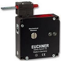
TZ1RE024M
Manufacturer Part Number
TZ1RE024M
Description
SAFETY SWITCH
Manufacturer
EUCHNER
Datasheet
1.NZ1HS-2131-M.pdf
(127 pages)
Specifications of TZ1RE024M
Operating Force Max
35N
Contact Voltage Ac Max
230V
Contact Voltage Dc Max
24V
Contact Current Ac Max
4A
Contact Current Dc Max
4A
Switch Terminals
Lead
Case Material
Aluminium, Diecasting


Appendix
Danger area
Any area in or around a machine in which a person is subject to a risk of
injury or a health hazard. The hazard can
Electrical locking
Locking using the open-circuit current principle.
Emergency release
The emergency release is used to unlock guard locking in an emergency.
The guard locking can be unlocked without tools.
Emergency unlocking
The emergency unlocking is used to unlock
emergency. The guard locking can be unlocked without tools and from
the access side. With the emergency unlocking, the switch engages in
the unlocked position and can only be reset to its original position after
an action similar to a repair.
Enabling switch
If a safety guard is open, movements are only to be possible if the controls
are operated continuously. These are controls with automatic return to their
original position. In general the term enabling switches is used here.
108
Either be present continuously on the correct use of the machine
(movement of hazardous moving parts, arcs during welding, etc.)
Or can occur unexpectedly (unintentional, unexpected starting, etc.).
Safety switch with guard locking and emergency unlocking
Safety switch with guard locking and emergency release
Enabling switch with +/– buttons
guard locking in an
Escape release
The escape release must make it possible to unlock the safety guard
from within the danger area without the use of tools. The device must be
manually operated and must positively act on the locking mechanism.
Actuation must not result in permanent disabling of the guard locking .
Guard locking
The guard locking retains a movable safety guard in the closed position
until the machine is no longer producing any risk of injury. With the guard
locking open, unintentional starting of the machine is prevented.
Guard locking monitoring
The guard locking monitoring monitors the position of the interlocking
solenoids. This device is positively linked to the switching element ÜK
via a locking arm. On intentional or unintentional unlocking of the interlo-
cking solenoid, the positively driven contact in this switching element is
actuated and therefore signals the position of the interlocking solenoid.
The sectional drawings show the safety switch TZ in its three switch
states:
Hazardous states
Are states that could result in injury. Safety switches , if the safety
guard is correctly used, prevent this hazard (cf. safe state ).
Door open and unlocked
Door closed and unlocked
Door closed and locked
SK
SK
SK
11
11
11
23
23
23
24
24
24
12
12
12
11
11
11
23
23
23
Guard locking
Guard locking
Guard locking
solenoid
solenoid
solenoid
24
24
24
ÜK
ÜK
12
ÜK
12
12
Related parts for TZ1RE024M
Image
Part Number
Description
Manufacturer
Datasheet
Request
R

Part Number:
Description:
ACTUATOR
Manufacturer:
EUCHNER
Datasheet:

Part Number:
Description:
ACTUATOR
Manufacturer:
EUCHNER
Datasheet:

Part Number:
Description:
ACTUATOR
Manufacturer:
EUCHNER
Datasheet:

Part Number:
Description:
ACTUATOR
Manufacturer:
EUCHNER
Datasheet:

Part Number:
Description:
JOYSTICK SWITCH
Manufacturer:
EUCHNER
Datasheet:

Part Number:
Description:
JOYSTICK SWITCH
Manufacturer:
EUCHNER
Datasheet:

Part Number:
Description:
JOYSTICK SWITCH
Manufacturer:
EUCHNER
Datasheet:

Part Number:
Description:
JOYSTICK SWITCH
Manufacturer:
EUCHNER
Datasheet:

Part Number:
Description:
JOYSTICK SWITCH
Manufacturer:
EUCHNER
Datasheet:


Part Number:
Description:
LIMIT SWITCH, SINGLE
Manufacturer:
EUCHNER
Datasheet:

Part Number:
Description:
SAFETY SWITCH
Manufacturer:
EUCHNER
Datasheet:

Part Number:
Description:
SAFETY SWITCH
Manufacturer:
EUCHNER
Datasheet:

Part Number:
Description:
SAFETY SWITCH
Manufacturer:
EUCHNER
Datasheet:

Part Number:
Description:
SAFETY SWITCH
Manufacturer:
EUCHNER
Datasheet: