TZ1RE024M EUCHNER, TZ1RE024M Datasheet - Page 56
TZ1RE024M
Manufacturer Part Number
TZ1RE024M
Description
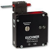
SAFETY SWITCH
Manufacturer
EUCHNER
Datasheet
1.NZ1HS-2131-M.pdf
(127 pages)
Specifications of TZ1RE024M
Operating Force Max
35N
Contact Voltage Ac Max
230V
Contact Voltage Dc Max
24V
Contact Current Ac Max
4A
Contact Current Dc Max
4A
Switch Terminals
Lead
Case Material
Aluminium, Diecasting


Safety Switches with Separate Actuator, Metal Housing
Safety switch TZ with guard locking and guard locking monitoring
Mechanical release
Is used for releasing the guard locking with the
aid of a tool. A sealing wire can be fitted to
protect against tampering. Lead sealing kit and
tool included.
Solenoid operating voltage and LED function
display
The following voltage ranges are available:
Locking methods
TZ1 Closed-circuit current principle, locking by
TZ2 Open-circuit current principle, locking by
Switching elements (see also page 11)
SK For monitoring the door/actuator position
ÜK For monitoring the guard locking (built-in solenoid)
For combinations available see ordering table:
Ordering table
Series
56
2131H Slow-action contact element
3131H Slow-action contact element
2121H Slow-action contact element 4 NC
110 V
230 V
TZ
Mechanical release on the front
Two LEDs, red and green
Plug connector optional
Actuating head fitted left or right
528H Slow-action contact element
24 V
spring force. Release by applying voltage
to the solenoid.
applying voltage to the solenoid. Release
by spring force.
Mechanical
Electrical
Locking
1 NC
3 NC
2 NC
AC/DC
1
2
AC
AC
Switch
+ 1 NO
+ 1 NO
+ 2 NO
head
Right
Right
Left
Left
RE
RE
LE
LE
-15%, +10%
-15%, +10%
-15%, +10%
SK: 528H, 1 NC
ÜK: 528H, 1 NC
SK: 2121H, 4 NC
ÜK: 2121H, 4 NC
SK: 2131H, 3 NC
ÜK: 3131H, 2 NC
SK: 528H, 1 NC
ÜK: 528H, 1 NC
SK: 2121H, 4 NC
ÜK: 2121H, 4 NC
SK: 2131H, 3 NC
ÜK: 3131H, 2 NC
SK: 528H, 1 NC
ÜK: 528H, 1 NC
SK: 2131H, 3 NC
ÜK: 3131H, 2 NC
SK: 528H, 1 NC
ÜK: 528H, 1 NC
SK: 2131H, 3 NC
ÜK: 3131H, 2 NC
Switching element
+ 1 NO
+ 1 NO
+ 1 NO
+ 1 NO
+ 1 NO
+ 1 NO
+ 1 NO
+ 1 NO
+ 1 NO
+ 2 NO
+ 1 NO
+ 2 NO
+ 1 NO
+ 2 NO
+ 1 NO
+ 2 NO
Cable entry M20 x 1.5
Dimension drawings
Wiring diagram
PE
nection
14
13
22
14
13
22
21
21
1
2
5
6
3
4
Con-
metr.
metr.
metr.
metr.
metr.
metr.
metr.
metr.
metr.
metr.
M
M
M
M
M
M
M
M
M
M
SK:528H/ÜK:528H
13
21
SK:528H
RD
Cable entry
M20 x 1.5
TZ1RE024MVAB
TZ2RE024MVAB
14
22
TZ1LE024MVAB
TZ2LE024MVAB
GN
Mechanical release
On request
On request
TZ1LE024M
TZ1RE024M
TZ2LE024M
TZ2RE024M
082 050
083 965
082 051
083 966
090 559
088 070
090 560
088 071
24 V
actuator inserted and locked
13
21
ÜK:528H
31
actuating head on left is a mirror image
20
14
22
TZ1LE110MVAB
TZ1RE110MVAB
TZ2LE110MVAB
TZ2RE110MVAB
Black cover
TZ1LE110M
On request
TZ1RE110M
On request
TZ2LE110M
TZ2RE110M
083 160
088 023
083 161
088 024
083 162
088 025
083 163
088 026
110 V
GN
SK:2121H/ÜK:2121H
35
RD
TZ1RE220MVAB
TZ1LE220MVAB
TZ2LE220MVAB
TZ2RE220MVAB
On request
TZ1RE220M
On request
TZ2RE220M
TZ1LE220M
TZ2LE220M
100
083 166
088 029
083 167
088 030
088 031
088 027
088 032
088 028
110
b
230 V
36
52
a
36
+4
18
25
±1
23
TZ1LE024MVFG-RC1925
TZ1RE024MVFG-RC1925
TZ1LE024MVAB-R
TZ1RE024MVAB-R
TZ1LE024M-R
TZ1RE024M-R
TZ2LE024M-R
TZ2RE024M-R
On request
On request
083 164
089 464
089 434
083 165
089 465
083 233
089 445
089 446
24 V
PE
12
11
22
21
34
33
42
41
14
13
22
21
34
33
42
41
2
5
6
3
4
Please order actuator
separately (see page 76)
a Travel without operation:
actuator is in the guide slot,
however function is not triggered.
b Switching operation completed:
actuator must be inserted to this
point to ensure reliable switching.
The actuator must be withdrawn at
least to point a for switching off.
1
SK:2131H/ÜK:3131H
Red cover
11
21
33
41
SK:2131H
RD
For cable glands see
page 82
12
22
34
42
GN
TZ1LE110M-R
TZ1RE110M-R
13
33
21
41
On request
On request
On request
On request
On request
On request
On request
On request
ÜK:3131H
083 168
089 448
110 V
14
34
22
42
Related parts for TZ1RE024M
Image
Part Number
Description
Manufacturer
Datasheet
Request
R

Part Number:
Description:
ACTUATOR
Manufacturer:
EUCHNER
Datasheet:

Part Number:
Description:
ACTUATOR
Manufacturer:
EUCHNER
Datasheet:

Part Number:
Description:
ACTUATOR
Manufacturer:
EUCHNER
Datasheet:

Part Number:
Description:
ACTUATOR
Manufacturer:
EUCHNER
Datasheet:

Part Number:
Description:
JOYSTICK SWITCH
Manufacturer:
EUCHNER
Datasheet:

Part Number:
Description:
JOYSTICK SWITCH
Manufacturer:
EUCHNER
Datasheet:

Part Number:
Description:
JOYSTICK SWITCH
Manufacturer:
EUCHNER
Datasheet:

Part Number:
Description:
JOYSTICK SWITCH
Manufacturer:
EUCHNER
Datasheet:

Part Number:
Description:
JOYSTICK SWITCH
Manufacturer:
EUCHNER
Datasheet:


Part Number:
Description:
LIMIT SWITCH, SINGLE
Manufacturer:
EUCHNER
Datasheet:

Part Number:
Description:
SAFETY SWITCH
Manufacturer:
EUCHNER
Datasheet:

Part Number:
Description:
SAFETY SWITCH
Manufacturer:
EUCHNER
Datasheet:

Part Number:
Description:
SAFETY SWITCH
Manufacturer:
EUCHNER
Datasheet:

Part Number:
Description:
SAFETY SWITCH
Manufacturer:
EUCHNER
Datasheet: