CES-A-BBA EUCHNER, CES-A-BBA Datasheet
CES-A-BBA
Specifications of CES-A-BBA


Related parts for CES-A-BBA


CES-A-BBA Summary of contents
Page 1
... Non-Contact More than safety. Safety Switches CES/CEM CES/CEM Transponder Coding ...
Page 2
... We familiar- ize ourselves with their needs, require- ments and products and we learn from the experiences of our cus- tomers’ own customers. EUCHNER – More than safety. Quality – made by EUCHNER ...
Page 3
... Read heads/actuators CES CES series read heads CES series actuators Read heads/actuators CEM Functional description CEM series read heads CEM series actuators Accessories Connection cables Plug connector Safety screws Insertion tool for actuator CES-A-BMB Appendix Definition of terms Index Technical Status 06-03/06 Contents ...
Page 4
... Transponder technology is also used on the non-contact safety switches series CES from EUCHNER and is an advanced solution for a new safety concept. Power is supplied and data transmitted to the coded actuator using a non-contact, inductive read head. The major advantage of the system is the battery-less actuator technology that will give the user many years of service-free operation ...
Page 5
... Non-Contact Safety Switches CES/CEM Your advantages Uniquely coded actuator Every actuator is unique Absolutely secure against tampering Homogeneous magnetic field It is possible to rotate the actuator within the operating distance of the read head Actuator and read head have a wide operating distance and a broad hysteresis ...
Page 6
... CES-A-BDA Page 46 Page 36 - Round design - ∅ Page 40 CES-A-BCA Page 44 - Cube-shaped design - PE-HD housing Page 38 CES-A-BBA Page 44 - Cube-shaped design - Fortron housing CES-A-BMB Page 47 - Cylindrical design M12 Subject to technical modifications; no responsibility is accepted for the accuracy of this information. Connection cables No additional connection cable necessary ...
Page 7
... PVC connection cable see page 65 Safety door actuator CES-A-BCA Page 44 M12 plug connector - PE-HD housing PVC connection cable see page 65 Safety door actuator CES-A-BBA Page 44 M12 plug connector - Fortron housing PVC connection cable see page 65 Position actuator CES-A-NBA Page 45 M12 plug connector ...
Page 8
... ERROR LED illuminates red. The safety contacts on the safety switch CES can switch currents from Since small currents can be switched, the user has the option of connecting the safety switch CES directly to a safe control system. Safe control systems will become increasingly important as technology progresses ...
Page 9
... Fault diagnostics possible using LED indicator Coded plug-in terminals Avoidance of faults in service Large operating distance (CES-A-ABA-01) and 15 mm (CES-A-ABA-01B) with additional hysteresis Large mechanical tolerances possible for door guide Approvals from BG, UL, SIBE Subject to technical modifications; no responsibility is accepted for the accuracy of this information. ...
Page 10
... Non-Contact Safety Switches CES/CEM Evaluation unit CES-A-ABA... Housing for DIN rail mounting Relay output 1 read head can be connected In combination with read head CES-A-L... and actuator CES-A-B.. Dimension drawing 22 24V 0V CES STATE OUT ERROR TST OUT ERR GND Suitable for 35 mm DIN rail ...
Page 11
... Non-Contact Safety Switches CES/CEM Technical data Parameters Housing material Dimensions Weight Ambient temperature Degree of protection to IEC/EN 60529 Degree of contamination / material group Mounting Number of read heads Connection (plug-in screw terminals/coded) Operating voltage U (regulated, residual ripple < For the approval according to the following applies ...
Page 12
... Non-Contact Safety Switches CES/CEM Wiring and block diagram CES-A-ABA... CES evaluation unit Operating voltage brown 24V 0V CPU-A KA 10kΩ 10kΩ TST OUT ERR GND 12 Illustration: Actuator not in the operating distance Screen connection white DDSP DDSP: CPU-B D ouble ynamic D S afety arth with fault ...
Page 13
... The testing of the internal function of the safety switch CES is not necessary because the device monitors itself in real time. Wear on an output contact (relay output) is detected by the device at the latest the next time the safety guard is opened ...
Page 14
... The safety contacts on the new evaluation unit can switch switching currents from Since small currents can be switched, the user has the option of connecting the safety switch CES directly to a safe control system. Safe control systems will become increasingly important as technology progresses. ...
Page 15
... Control system can poll the state of the safety guard Fault diagnostics possible using LED indicator Large operating distance and 15 mm with additional hysteresis Large mechanical tolerances possible for door guide Approvals from BG, UL, SIBE Subject to technical modifications; no responsibility is accepted for the accuracy of this information. ...
Page 16
... Non-Contact Safety Switches CES/CEM Evaluation unit CES-A-AEA-02B Housing for DIN rail mounting Relay output 2 read heads can be connected In combination with read head CES-A-L... and actuator CES-A-B.. Dimension drawing 45 Suitable for 35 mm DIN rail according to EN 50022-35 Notes on the electrical connection All the electrical connections must either be isolated from the mains supply by a safety transformer according to EN/IEC 61558 with limited output voltage in the event of a fault other equivalent isolation measures ...
Page 17
... Non-Contact Safety Switches CES/CEM Technical data Parameters Housing material Dimensions Weight Ambient temperature Atmospheric humidity Degree of protection to IEC/EN 60529 Degree of contamination / material group Mounting Number of read heads Connection (screw terminals) Operating voltage U (regulated, residual ripple < For the approval according to the following applies ...
Page 18
... Non-Contact Safety Switches CES/CEM Evaluation unit CES-A-AEA-04B Housing for DIN rail mounting Relay output 4 read heads can be connected In combination with read head CES-A-L... and actuator CES-A-B.. Dimension drawing 45 Suitable for 35 mm DIN rail according to EN 50022-35 Notes on the electrical connection All the electrical connections must either be isolated from the mains supply by a safety transformer according to EN/IEC 61558 with limited output voltage in the event of a fault other equivalent isolation measures ...
Page 19
... Non-Contact Safety Switches CES/CEM Technical data Parameters Housing material Dimensions Weight Ambient temperature Atmospheric humidity Degree of protection to IEC/EN 60529 Degree of contamination / material group Mounting Number of read heads Connection (screw terminals) Operating voltage U (regulated, residual ripple < For the approval according to the following applies ...
Page 20
... Non-Contact Safety Switches CES/CEM Wiring and block diagram CES-A-AEA-02B Activation of the teach-in operation with bridges on J1, J2 Operating voltage H1a STA DIA DIP switches TST O1 Semiconductor monitoring outputs +UB, 0V Power supply J1,J2 Bridges for teach-in operation H1a,H1b..H2a,H2b Connection, read heads 1...2 SH1,SH2 ...
Page 21
... Non-Contact Safety Switches CES/CEM Wiring and block diagram CES-A-AEA-04B Activation of the teach-in operation with jumper on J1, J2 Operating voltage Semiconductor monitoring outputs +UB Power supply J1,J2 Jumper for teach-in operation H1a,H1b..H4a,H4b Connection for read heads 1..4 SH1,SH2,SH3,SH4 Screen TST Testinput O1..O4 Semiconductor monitoring outputs ...
Page 22
... Setup procedure During setup, the parameters are set in the evaluation unit by the user using a teach-in operation (number of connected read heads, assignment of the actuators to the read heads, with or without automatic start, with or without feedback loop). During this process the read heads are activated. ...
Page 23
... The testing of the internal function of the safety switch CES is not necessary because the device monitors itself in real time. Wear on an output contact (relay output) is detected by the device at the latest the next time the safety guard is opened. A short circuit in the output cable is not detected by the device ...
Page 24
... The information from the coded actuator is read by the evaluation unit and processed at the same point. The transfer of static signals (information on whether door open or closed) to the higher level switchgear permits the use of connecting cables up to 300 m long with the system ...
Page 25
... Two redundant design semiconductor outputs (safety outputs) with internal monitoring: CES-A-C5E-01: Safety category 3 according to EN 954-1 (according to BG and SIBE Switzerland) CES-A-C5H-01: Safety category 4 according to EN 954-1 (according to BG and SIBE Switzerland) Read head and evaluation unit form a compact unit Reduction of wiring faults during setup ...
Page 26
... EN/IEC 61558 with limited output voltage in the event of a fault other equivalent isolation measures common power supply is used, all the inductive and capacitive loads (e.g. contactors) connected to the power supply must be connected to appropriate interference suppression units. Typical operating distance (only in conjunction with actuator CES-A-BBA) m Actuator s Read ...
Page 27
... Non-Contact Safety Switches CES/CEM Technical data Parameters Housing material Dimensions Weight Ambient temperature Degree of protection to IEC/EN 60529 Safety class according to IEC/EN 61558 Installation position Connection type Operating voltage U (reverse polarity protected, B regulated, residual ripple < For the approval according to the following applies ...
Page 28
... Non-Contact Safety Switches CES/CEM Wiring and block diagram CES-A-C5... Coded actuator Read head with Read head evaluation unit CES-A-C5... Housing 118 Connection: M 12x1 8-pin, screened View on the safety switch's plug Illustration: Actuator not in the operating distance Trans- ponder Output circuit: +LA LA ...
Page 29
... Non-Contact Safety Switches CES/CEM System functions safety switches CES-A-C5... and CES-A-S5... Teach-in function for actuator The actuator must be allocated to the evaluation unit using a teach- in function before the system forms a functional unit. During a teach-in operation, the safety outputs and the door monitoring output OUT are LOW, i.e. the system is in the safe state ...
Page 30
... The position actuators (dogs) are mounted at the necessary positions of the moving part of the safety guard. The safety actuator is fitted with the safety guard in the closed position result the roller door can be closed at high speed (max ...
Page 31
... Non-Contact Safety Switches CES/CEM Your advantages Safety and identification functions integrated into one switch Detection of 14 different position actuators High approach speed (2.0 m/s) of the position actuators Safety switch in standard housing according to EN 60947-5-2 Read head and evaluation unit form a compact unit ...
Page 32
... Safety Switch CES-A-S5H-01 Safety and identification functions Read head and evaluation unit integrated in the standard housing Semiconductor output Connection using 12-pin plug connector (Plug connector see page 66) In combination with safety actuator CES-A-BBA and position actuator CES-A-NBA-. Dimension drawing 40,5 40 LED status ...
Page 33
... Non-Contact Safety Switches CES/CEM Technical data Parameters Housing material Dimensions Weight Ambient temperature Degree of protection according to IEC/EN 60529 Safety class according to IEC/EN 61558 Installation position Connection type Operating voltage U (reverse polarity protected, B regulated, residual ripple < Current consumption External fuse (operating voltage) ...
Page 34
... Non-Contact Safety Switches CES/CEM Wiring and block diagram CES-A-S5... Coded actuator Read head with evaluation unit CES-A-S5H-01 Connection: M23 plug connector 12-pin, screened D0 PLC D1 control system D2 D3 +LA + Transponder Output circuit for output A: Read coil Safety DDSP Read head Double Dynamic Safety Path ...
Page 35
... Non-Contact Safety Switches CES/CEM LEDs Safety switch LED displays LED labels STATE Green flashing OUT/ERROR Position sensor LED displays LED labels D0, D1, D2, D3 Allocation table Allocation of the actuator numbers to the safety outputs and data outputs Actuator Safety actuator Actuator 2 Actuator 3 Actuator 4 ...
Page 36
... Cube-shaped design Hard-wired cable In combination with evaluation units CES-A-A... and actuators CES-A-BBA Dimension drawing type CES-A-LNA... "l" 42 CES-A-L XXXXXX 32 ±0,1 2 safety screws M4x14 included Typical operating distance With evaluation unit CES-A-ABA-01 and actuator CES-A-BBA m Actuator s Read head Switch-off 8 distance Hysteresis OFF 6 Switch-on ...
Page 37
... Degree of protection Installation position Method of operation Dynamic data transfer to the evaluation unit Power supply Dwell time 1) Operating distance for center offset (evaluation unit CES-A-ABA-01 with CES-A-BBA) - Safe switch-off distance S ar Cable length Switch-on distance Switching hysteresis Cable length l ≥ Switch-on distance S ...
Page 38
... In combination with evaluation units CES-A-A... and actuators CES-A-BBA Dimension drawing type CES-A-LNA-SC 32 ±0,1 6,8 CES-A-L 077715 A0 min.38 2 safety screws M4x14 included CES-A-L 077715 A0 Typical operating distance With evaluation unit CES-A-ABA-01 and actuator CES-A-BBA m Actuator s Read head Switch-off 8 distance Hysteresis OFF 6 Switch-on distance ...
Page 39
... Degree of protection Installation position Method of operation Dynamic data transfer to the evaluation unit Power supply Dwell time 1) Operating distance for center offset (Evaluation unit CES-A-ABA-01 with CES-A-BBA) - Safe switch-off distance S ar Cable length Switch-on distance Switching hysteresis Cable length l ≥ Switch-on distance S ...
Page 40
... CES-A-BCA Dimension drawing type CES-A-LCA... 48 42 ± 0,1 32 Flat Active seal face l 2 safety screws M4x14 included Flat seal included Typical operating distance With evaluation unit CES-A-ABA-01 and actuator CES-A-BBA m Actuator s Read head Switch-off 8 distance Hysteresis OFF 6 Switch-on distance ...
Page 41
... Degree of protection Installation position Method of operation Dynamic data transfer to the evaluation unit Power supply Dwell time 1) Operating distance for center offset (Evaluation unit CES-A-ABA-01 with CES-A-BBA) - Safe switch-off distance S ar Cable length Switch-on distance Switching hysteresis Cable length l ≥ Switch-on distance S ...
Page 42
... EMC during assembly (see page 66). Intermediate terminals must not be used. Actuator and read head must be fitted so that: The active faces (front faces) are at the switch-on distance 0 closer (see a0 technical data) with the safety guard closed. They are not used as a mechanical stop. ...
Page 43
... Installation position Method of operation Dynamic data transfer to the evaluation unit Power supply Dwell time 1) Operating distance for center offset (Evaluation unit CES-A-ABA-01 with CES-A-BMB) - Safe switch-off distance S ar Cable length Switch-on distance Switching hysteresis Operating distance for center offset (Evaluation unit CES-A-ABA-01B/CES-A-AEA-04B ...
Page 44
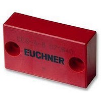
... Non-Contact Safety Switches CES/CEM Actuator CES-A-BBA / CES-A-BCA Cube-shaped design CES-A-BCA suitable for use in aggressive media (e.g. acids, alkaline) In combination with evaluation units CES-A-A..., read head CES-A-LNA... and safety switches CES-A-C5... Dimension drawing CES-A-BBA 42 CES-A-B 071840 32 ±0,1 Active 2 safety screws M4x14 face ...
Page 45
... Actuator and read head must be fitted so that: The active faces (front faces) are at the switch-on distance 0 closer (see a0 technical data) with the safety guard closed. They are not used as a mechanical stop. They are positively mounted on the safety guard, e.g. by using the safety screws included ...
Page 46
... Centre offset m [mm] Switching distances with read head cable length Surrounding material / installation method Switch-on distance s min./typ. a0 Switching hysteresis min./typ. Safe switch-off distance s max With a cable length from the values for the switch-on distance and the switching hysteresis reduce the value given. ...
Page 47
... Subject to technical modifications; no responsibility is accepted for the accuracy of this information. Notes on installation Actuator and read head must be fitted so that: 0,80 The active faces (front faces) are at the switch-on distance 0 technical data) with the safety guard closed. They are not used as a mechanical stop. They are positively connected to the safety guard, e ...
Page 48
... Depending on the switch design – EUCHNER provides two diffe- rent housing sizes – adhesive forces of approx. 500 N or 1000 N respectively are applied between the CEM actuator and the CEM read head. Practical experience has shown that these magnetic adhesive forces effectively prevent any opening, even if the user applies an enormous amount of effort ...
Page 49
... Absolutely secure against tampering Very high level of safety with one switch With evaluation unit CES-A-ABA-01B safety category 3 according to EN 954-1 With evaluation unit CES-A-AEA-02B and CES-A-AEA-04B safety category 4 according to EN 954-1 Integrated solenoid for process protection Unintentional opening of the safety door is prevented ...
Page 50
... For detailed information see the operating instructions for the CES evaluation unit used. Notes on installation The connection cable to the CES evaluation unit must only must be extended using EUCHNER plug connectors and adequate consideration must be given to EMC during assembly (see page 66) ...
Page 51
... Non-Contact Safety Switches CES/CEM Technical data Parameters General Housing material Material, read head CES Solenoid material Weight Ambient temperature Degree of protection according to IEC 60529 Installation position Solenoid Adhesive force in axial direction Adhesive force due to remanence 1) Solenoid center offset max. Solenoid operating voltage U ...
Page 52
... For detailed information see the operating instructions for the CES evaluation unit used. Notes on installation The connection cable to the CES evaluation unit must only be extended using EUCHNER plug connectors and adequate considerati- on must be given to EMC during assembly. ...
Page 53
... Non-Contact Safety Switches CES/CEM Technical data Parameters General Housing material Material, read head CES Solenoid material Weight Ambient temperature Degree of protection according to IEC 60529 Installation position Solenoid Adhesive force in axial direction Adhesive force due to remanence Solenoid center offset max. Solenoid operating voltage U ...
Page 54
... LED. For detailed information see the operating instructions for the CES evaluation unit used. Notes on installation The connection cable to the CES evaluation unit must only must be extended using EUCHNER plug connectors and adequate consideration must be given to EMC during assembly (see page 66) ...
Page 55
... Non-Contact Safety Switches CES/CEM Technical data Parameters General Housing material Material, read head CES Solenoid material Weight Ambient temperature Degree of protection according to IEC 60529 Installation position Solenoid Adhesive force in axial direction Adhesive force due to remanence 1) Solenoid center offset max. Solenoid operating voltage U ...
Page 56
... LED. For detailed information see the operating instructions for the CES evaluation unit used. Notes on installation The connection cable to the CES evaluation unit must only be extended using EUCHNER plug connectors and adequate consideration must be given to EMC during assembly. Intermediate terminals must not be used. ...
Page 57
... Non-Contact Safety Switches CES/CEM Technical data Parameters General Housing material Material, read head CES Solenoid material Weight Ambient temperature Degree of protection according to IEC 60529 Installation position Solenoid Adhesive force in axial direction Adhesive force due to remanence Solenoid center offset max. Solenoid operating voltage U ...
Page 58
... Non-Contact Safety Switches CES/CEM Wiring and block diagram CEM (connection of read head CEM-A-LD4-S2 to evaluation unit CES-A-AEA-04B) CES Trans- Trans- ponder ponder Activation of the teach-in operation Head 1 with bridges on J1, J2 Operating voltage H1a UB 0V LED STA DIA DIP switches TST O1 O2 Semiconductor ...
Page 59
... Non-Contact Safety Switches CES/CEM Connection variants read head CEM-A-LE05K-S2 Cable outlet, straight plug connector Connection cable Connection cable Solenoid operating Evaluation unit voltage CES-A-KSB... Connection variants read head CEM-A-LH10K-S3 Cable outlet, straight plug connector Connection cable LED indicator Connection cable Connection cable ...
Page 60
... The actuators CEM... can only be used with the evaluation units given above. 50 For detailed information see the operating 40 ±0,10 instructions for the CES evaluation unit used. 5,4 Notes on installation Actuator and read head must be fitted so that: They are positively connected to the safety guard, e ...
Page 61
... Subject to technical modifications; no responsibility is accepted for the accuracy of this information. Note The actuators CEM... can only be used with the evaluation units given above. For detailed information see the operating 65 instructions for the CES evaluation unit used. 52 ±0,15 5,4 Notes on installation Actuator and read head must be fitted so ...
Page 62
... Non-Contact Safety Switches CES/CEM Accessories Connection cable with M8 plug connector for solenoid operating voltage on read head CEM... Straight plug connector 4 (BK) 2 (WH) 1 (BN) 3 (BU) M8 female connector View of connection side Angled plug connector 8 2 (WH) 4 (BK) 1 (BN) 3 (BU) View of connection side M8 female connector ...
Page 63
... Non-Contact Safety Switches CES/CEM Connection cable with M8 plug connector for LED indicator on read head CEM-A-LH10K-S3 Straight plug connector 2 (WH) 4 (BK) 3 (BU) 1 (BN) M8 plug View of connection side Angled plug connector 8,8 2 (WH) 4 (BK) 3 (BU) 1 (BN) View of connection side Technical data Parameters Plug connector ...
Page 64
... Non-Contact Safety Switches CES/CEM Connection cable with M8 plug connector for read head CES-A-L... and CEM-A-L 31 22,5 M8 female connector Angled plug connector 26,5 ∅10 M8 female connector Technical data Parameters Plug connector Connection cable Cable length Ordering table Cable length "l" Plug connector ...
Page 65
... Non-Contact Safety Switches CES/CEM Connection cable with M12 plug connector for safety switch CES-A-C5... OUT + -LAB View on connection side of the +LB 8-pin female connector Safety switch CES-A-C5... Voltage drop as a function of switching current and cable length (examples) Switching current Cable length "l" ...
Page 66
... Screw type Use for read head CES-A-L... M4x14 for read head CES-A-B... for actuator CES-A-BBA Insertion tool for actuator CES-A-BMB With the aid of the insertion tool, the actuator CES-A-BMB (cylindrical design) can be screwed into a prepared M12 x 0.75 thread in safety doors. +0,12 ...
Page 67
... PDF proximity devices with automatic control that do not lose their defined behavior in spite of several faults (see EN 60 947-5-3). PDF-S PDF proximity devices that do not lose their defined behavior in spite of a single fault (see EN 60947 5 3). Safety class III Equipment of safety class III is equipment on which protection against electric shock is based on safety extra-low voltage and is equipment in which no voltages higher than the safety extra- low voltage are produced ...
Page 68
... Non-Contact Safety Switches CES/CEM Index sorted by article Item CEM-A-LH10K-S3 CEM-A-LH10R-S3 CES-A-ABA-01 CES-A-ABA-01B CES-A-AEA-02B CES-A-AEA-04B CES-A-BBA CES-A-BCA CES-A-BDA CES-A-BMB CES-A-C5E-01 CES-A-C5H-01 CES-A-KSB-03V CES-A-KSB-05P CES-A-KSB-05V CES-A-KSB-10P CES-A-KSB-10V CES-A-KSB-15P CES-A-KSB-20P CES-A-KSB-20V CES-A-KSB-25P CES-A-KSB-25V CES-A-KSB-50P CES-A-KSB-50V CES-A-KWB-10V CES-A-LCA-10V CES-A-LMN-SC CES-A-LNA-05P CES-A-LNA-05V CES-A-LNA-10P CES-A-LNA-10V CES-A-LNA-15P CES-A-LNA-15V ...
Page 69
... Non-Contact Safety Switches CES/CEM Index sorted by catalog number Order No. Item 037 662 Insertion tool for actuator CES-A-BMB 071 840 CES-A-BBA 071 845 CES-A-LNA-05V 071 846 CES-A-LNA-10V 071 847 CES-A-LNA-15V 071 850 CES-A-ABA-01 071 863 Safety screws M4x14-CES/V20 071 975 CES-A-LNA-25V 072 000 ...
Page 70
... Hong Kong Tel. +01-519-966-3444 Tel. +852-2889-0292 Fax +01-519-966-6160 Fax +852-2889-1814 sales@iacnassociates.com info@imperial-elec.com China Hungary EUCHNER Electric (Shanghai) Ltd. EUCHNER Ges.mbH No. 8 High Technology Zone Magyarországi Fióktelep No. 503 Meinengda Road 2045 Törökbálint Songjiang, Shanghai, 201613 Tópark utca 1/a. Tel. +86-(0)21-5774-7090 Tel ...
Page 71
... offic He d offic d offic offic offic EUCHNER GmbH + Co. KG Kohlhammerstraße 16 70771 Leinfelden-Echterdingen Germany Tel. +49-(0)711-7597-0 Fax +49-(0)711-753316 info@euchner.de www.euchner.de www www www euc euc euc hner hner hner om om www www euc euchner hner om om More than safety. More than safety. More than safety. Mor than safety ...