PD3-109-57-RS TRINAMIC, PD3-109-57-RS Datasheet - Page 12
PD3-109-57-RS
Manufacturer Part Number
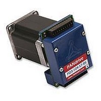
PD3-109-57-RS
Description
STEPPER MOTOR, PANDRIV, 57MM, 1.63NM
Manufacturer
TRINAMIC
Datasheet
1.PD3-109-57-RS.pdf
(16 pages)
Specifications of PD3-109-57-RS
Torque Max
1.63N-m
Current Rating
3A
No. Of Phases
2
External Depth
57mm
External Length / Height
78.5mm
External Width
57mm
Holding Torque
1.63N-m
Steps Per Revolution
RoHS Compliant
Coil Type
Bipolar
Svhc
No SVHC (15-Dec-2010)
Rohs Compliant
Yes


PD-109-57 / TMCM-109-57 Manual (V1.07 / Jul 18th, 2006)
5.2 Power Supply Requirements
The TMCM-109 is equipped with a switching voltage regulator that generates the 5V supply voltage
for the digital components of the module from the motor power supply. So only one supply voltage is
needed for the module. The power supply voltage can be 18..55V DC. Please note that there is no
protection against reverse polarity or too high voltage. The power supply typically should be within a
range of 24 to 48V to achieve highest motor performance. When using supply voltages near the upper
limit, a regulated power supply becomes a must. Please ensure, that enough power filtering capacitors
are provided in the system (2200µF or more recommended), in order to absorb mechanical energy fed
back by the motor in stalling conditions. In larger systems a zener diode circuitry might be required,
when motors are operated at high velocities.
The power supply should be designed in a way, that it supplies the nominal motor voltage at the
desired maximum motor power. In no case shall the supply value exceed the upper / lower voltage
limit. To ensure reliable operation of the unit, the power supply has to have a sufficient output
capacitor and the supply cables should have a low resistance, so that the chopper operation does not
lead to an increased power supply ripple directly at the unit. Power supply ripple due to the chopper
operation should be kept at a maximum of a few 100mV.
Therefore we recommend to
5.3 Disable
The disable input works as an emergency shutdown. The polarity can be configured using TMCL
(please see the TMCL Reference and Programming Manual for details).
It is in the users responsibility to stop the step impulses or set the velocity to zero before enabling the
motor again, because it would start abruptly or loose track otherwise.
5.4 Communication Interface – RS232 and RS485
The communication between the host and the module takes place via its host interface. This can be
either RS232 or RS485. The module is equipped with both interfaces, but only one interface can be
used at a time. All interfaces integrated on the module are ready-to-use, so there are no external
drivers or level shifters necessary. To select RS232, leave open the interface selection pin, for RS485
pull it to ground. Please see chapter 3.3 for the pin assignments of the interfaces.
Communication with the TMCM-109 module is done using TMCL commands. Refer to TMCL manual
for detailed information (8 References). When using the RS485 interface, the devices can be daisy-
chained. Bus termination resistors in the range of 100 Ohms are typically required at each of the two
ends of the cables.
Copyright © 2006, TRINAMIC Motion Control GmbH & Co. KG
a) keep power supply cables as short as possible
b) use large diameter for power supply cables
c) if the distance to the power supply is large (i.e. more than 2-3m), use a robust 2200µF or
larger additional filtering capacitor located near to the motor driver unit.
polarity 1
(connector 2, terminal 2)
Interface selection pin
V
OPTON
pulled to ground
open wire
open wire
polarity 2
Selected communication
V
OPTOFF
interface
RS232
RS485
12
Related parts for PD3-109-57-RS
Image
Part Number
Description
Manufacturer
Datasheet
Request
R

Part Number:
Description:
57mm / NEMA23 Stepper Motor with Controller / Driver and Serial Interface
Manufacturer:
TRINAMIC [TRINAMIC Motion Control GmbH & Co. KG.]
Datasheet:
Part Number:
Description:
57mm/NEMA23 or 60mm/NEMA24 Stepper Motor with Controller/Driver with Encoder and Serial Interface
Manufacturer:
TRINAMIC [TRINAMIC Motion Control GmbH & Co. KG.]
Datasheet:
Part Number:
Description:
60mm/NEMA24 Stepper Motor with Controller/Driver, with Encoder and Serial Interface
Manufacturer:
TRINAMIC [TRINAMIC Motion Control GmbH & Co. KG.]
Datasheet:
Part Number:
Description:
42mm/NEMA17 Stepper Motor with Controller/Driver, Encoderand Serial Interface
Manufacturer:
TRINAMIC [TRINAMIC Motion Control GmbH & Co. KG.]
Datasheet:
Part Number:
Description:
42mm/NEMA17 High Performance BLDC Motor with Controller/Driver and Serial Interface
Manufacturer:
TRINAMIC [TRINAMIC Motion Control GmbH & Co. KG.]
Datasheet:
Part Number:
Description:
42mm / NEMA17 Stepper Motor with Controller / Driver and Serial Interface
Manufacturer:
TRINAMIC [TRINAMIC Motion Control GmbH & Co. KG.]
Datasheet:
Part Number:
Description:
57mm diameter BLDC Encoder Motor with Controller/Driver and Serial Interface
Manufacturer:
TRINAMIC [TRINAMIC Motion Control GmbH & Co. KG.]
Datasheet:

Part Number:
Description:
2.54mm Pitch Power Board To Boardconnector
Manufacturer:
DDK Ltd.
Datasheet:
Part Number:
Description:
28mm Nema11 Stepper Motor With Controller Driver Serial Interface
Manufacturer:
ETC-unknow
Datasheet:
Part Number:
Description:
3-way Wilkinson Power Divider
Manufacturer:
Marki Microwave
Datasheet:
Part Number:
Description:
3-way Wilkinson Power Divider
Manufacturer:
Marki Microwave
Datasheet: