PD3-109-57-RS TRINAMIC, PD3-109-57-RS Datasheet - Page 14
PD3-109-57-RS
Manufacturer Part Number
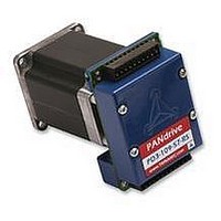
PD3-109-57-RS
Description
STEPPER MOTOR, PANDRIV, 57MM, 1.63NM
Manufacturer
TRINAMIC
Datasheet
1.PD3-109-57-RS.pdf
(16 pages)
Specifications of PD3-109-57-RS
Torque Max
1.63N-m
Current Rating
3A
No. Of Phases
2
External Depth
57mm
External Length / Height
78.5mm
External Width
57mm
Holding Torque
1.63N-m
Steps Per Revolution
RoHS Compliant
Coil Type
Bipolar
Svhc
No SVHC (15-Dec-2010)
Rohs Compliant
Yes


PD-109-57 / TMCM-109-57 Manual (V1.07 / Jul 18th, 2006)
5.7 Reference Switches
Two digital reference / stop switch inputs are provided (StopL= stop left and StopR = stop right). They
are used as an absolute position reference for homing and to set a hardware limit for the motion
range. The inputs have internal pullup resistors. Either opto-switches or mechanical switched with
normally closed contact can be used. The 5V output can be used as an supply for opto-switches.
5.8 StallGuard™ - Sensorless Motor Stall Detection
The integrated StallGuard™ feature gives a simple means to detect mechanical blocking of the motor.
This can be used for precise absolute referencing, when no reference switch is available. The load
value can be read using a TMCL command or the module can be programmed so that the motor will
be stopped automatically when it has been obstructed or the load has been too high. Just activate
StallGuard and then let the traveller run against a mechanical obstacle that is placed at the end of the
operation area. When the motor has stopped it is definitely at the end of its way, and this point can be
used as the reference position.
Please see the TMCL Reference and Programming Manual on how to activate the StallGuard feature.
The TMCL IDE also has some tools which let you try out and adjust the StallGuard function in an easy
way. This is also described in the TMCL Reference and Programming Manual.
5.9 Environment Temperature Considerations
As the power dissipation of the MOSFETs is very low, no heat sink or cooling fan is needed, unless
environment temperature is raised and the module continuously is operated at a high current.
When the output bridge temperature reaches a critical value, the output current is reduced by 20%. If
the temperature still rises higher, the outputs become switched off. The coils are automatically
switched on again when the temperature is within the limits again. An optional cooling fan can be
mounted to cope with higher environment temperatures, when problems are perceived. The 5V power
supply output can be used to operate a small fan.
5.10 LEDs
The TMCM-109 module is equipped with four LEDs that show the actual state of the module:
LED
POWER
CPU_OK
ERROR
OUT_0
Copyright © 2006, TRINAMIC Motion Control GmbH & Co. KG
Function
Shows that the module is powered
Flashes during normal operation. After resetting the configuration EEPROM it may
take some seconds before the LED starts flashing again. When the operating system
is being downloaded to the module the LED lights steadily.
On when the temperature of the MOSFETs is getting too high. The LED is off during
normal operation
Shows the state of the general purpose output
14
Related parts for PD3-109-57-RS
Image
Part Number
Description
Manufacturer
Datasheet
Request
R

Part Number:
Description:
57mm / NEMA23 Stepper Motor with Controller / Driver and Serial Interface
Manufacturer:
TRINAMIC [TRINAMIC Motion Control GmbH & Co. KG.]
Datasheet:
Part Number:
Description:
57mm/NEMA23 or 60mm/NEMA24 Stepper Motor with Controller/Driver with Encoder and Serial Interface
Manufacturer:
TRINAMIC [TRINAMIC Motion Control GmbH & Co. KG.]
Datasheet:
Part Number:
Description:
60mm/NEMA24 Stepper Motor with Controller/Driver, with Encoder and Serial Interface
Manufacturer:
TRINAMIC [TRINAMIC Motion Control GmbH & Co. KG.]
Datasheet:
Part Number:
Description:
42mm/NEMA17 Stepper Motor with Controller/Driver, Encoderand Serial Interface
Manufacturer:
TRINAMIC [TRINAMIC Motion Control GmbH & Co. KG.]
Datasheet:
Part Number:
Description:
42mm/NEMA17 High Performance BLDC Motor with Controller/Driver and Serial Interface
Manufacturer:
TRINAMIC [TRINAMIC Motion Control GmbH & Co. KG.]
Datasheet:
Part Number:
Description:
42mm / NEMA17 Stepper Motor with Controller / Driver and Serial Interface
Manufacturer:
TRINAMIC [TRINAMIC Motion Control GmbH & Co. KG.]
Datasheet:
Part Number:
Description:
57mm diameter BLDC Encoder Motor with Controller/Driver and Serial Interface
Manufacturer:
TRINAMIC [TRINAMIC Motion Control GmbH & Co. KG.]
Datasheet:

Part Number:
Description:
2.54mm Pitch Power Board To Boardconnector
Manufacturer:
DDK Ltd.
Datasheet:
Part Number:
Description:
28mm Nema11 Stepper Motor With Controller Driver Serial Interface
Manufacturer:
ETC-unknow
Datasheet:
Part Number:
Description:
3-way Wilkinson Power Divider
Manufacturer:
Marki Microwave
Datasheet:
Part Number:
Description:
3-way Wilkinson Power Divider
Manufacturer:
Marki Microwave
Datasheet: