PD3-109-57-RS TRINAMIC, PD3-109-57-RS Datasheet - Page 13
PD3-109-57-RS
Manufacturer Part Number
PD3-109-57-RS
Description
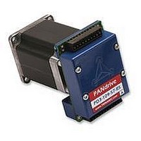
STEPPER MOTOR, PANDRIV, 57MM, 1.63NM
Manufacturer
TRINAMIC
Datasheet
1.PD3-109-57-RS.pdf
(16 pages)
Specifications of PD3-109-57-RS
Torque Max
1.63N-m
Current Rating
3A
No. Of Phases
2
External Depth
57mm
External Length / Height
78.5mm
External Width
57mm
Holding Torque
1.63N-m
Steps Per Revolution
RoHS Compliant
Coil Type
Bipolar
Svhc
No SVHC (15-Dec-2010)
Rohs Compliant
Yes


PD-109-57 / TMCM-109-57 Manual (V1.07 / Jul 18th, 2006)
5.5 Motor Current setting
The motor current can be set in a range of 0 to 255, using the TMCL software. 255 corresponds to the
module’s maximum I
5.6 Step / Direction Interface
5.6.1 Direction Input
The direction signal changes the motors rotation from clockwise (CW) to counterclockwise (CCW) and
vice versa. A change in the direction signal has to be aligned to the step pulse in order to specify the
direction of each step (please refer to setup -/ hold times).
5.6.2 Step Input
The step signal directly influences the velocity and acceleration of the motor. The velocity depends on
the frequency, the acceleration on the frequency’s change per time.
Frequency: The maximum step input frequency is 350 kHz. The minimum logic ”0” time is 0.7 µs and
the minimum logic “1” time is 2.0 µs.
Copyright © 2006, TRINAMIC Motion Control GmbH & Co. KG
direction
step pulse
motor CW
Extern
V
Intern
OPTON
0.7µs min
COIL
setting.
V
HIGH
GND
OPTON
Figure 5.2: Step and Direction Signal
Table 5.1: Motor Current Examples
same minimum times as above
Setting
2.0µs min
255
216
180
144
108
72
motor CCW
0
open wire
GND
I
COIL,PP
5.0A
4.2A
3.5A
2.8A
2.1A
1.4A
0A
0.7µs min
LOW
I
COIL,RMS
3.54A
3.0A
2.5A
2.0A
1.5A
1.0A
0A
V
OPTOFF
2.0µs min
13
Related parts for PD3-109-57-RS
Image
Part Number
Description
Manufacturer
Datasheet
Request
R

Part Number:
Description:
57mm / NEMA23 Stepper Motor with Controller / Driver and Serial Interface
Manufacturer:
TRINAMIC [TRINAMIC Motion Control GmbH & Co. KG.]
Datasheet:
Part Number:
Description:
57mm/NEMA23 or 60mm/NEMA24 Stepper Motor with Controller/Driver with Encoder and Serial Interface
Manufacturer:
TRINAMIC [TRINAMIC Motion Control GmbH & Co. KG.]
Datasheet:
Part Number:
Description:
60mm/NEMA24 Stepper Motor with Controller/Driver, with Encoder and Serial Interface
Manufacturer:
TRINAMIC [TRINAMIC Motion Control GmbH & Co. KG.]
Datasheet:
Part Number:
Description:
42mm/NEMA17 Stepper Motor with Controller/Driver, Encoderand Serial Interface
Manufacturer:
TRINAMIC [TRINAMIC Motion Control GmbH & Co. KG.]
Datasheet:
Part Number:
Description:
42mm/NEMA17 High Performance BLDC Motor with Controller/Driver and Serial Interface
Manufacturer:
TRINAMIC [TRINAMIC Motion Control GmbH & Co. KG.]
Datasheet:
Part Number:
Description:
42mm / NEMA17 Stepper Motor with Controller / Driver and Serial Interface
Manufacturer:
TRINAMIC [TRINAMIC Motion Control GmbH & Co. KG.]
Datasheet:
Part Number:
Description:
57mm diameter BLDC Encoder Motor with Controller/Driver and Serial Interface
Manufacturer:
TRINAMIC [TRINAMIC Motion Control GmbH & Co. KG.]
Datasheet:

Part Number:
Description:
2.54mm Pitch Power Board To Boardconnector
Manufacturer:
DDK Ltd.
Datasheet:
Part Number:
Description:
28mm Nema11 Stepper Motor With Controller Driver Serial Interface
Manufacturer:
ETC-unknow
Datasheet:
Part Number:
Description:
3-way Wilkinson Power Divider
Manufacturer:
Marki Microwave
Datasheet:
Part Number:
Description:
3-way Wilkinson Power Divider
Manufacturer:
Marki Microwave
Datasheet: