IP20 SOLA HEVI DUTY, IP20 Datasheet - Page 21
IP20
Manufacturer Part Number
IP20
Description
Fuse Cover Kit
Manufacturer
SOLA HEVI DUTY
Datasheet
1.RELAY_CARD-INT.pdf
(46 pages)
Specifications of IP20
Peak Reflow Compatible (260 C)
No
Kit Contents
2 Covers And Thread Forming Screws
Leaded Process Compatible
No
For Use With
SBE Fuse Block
Lead Free Status / RoHS Status
Lead free / RoHS Compliant
Available stocks
Company
Part Number
Manufacturer
Quantity
Price

Part Number:
IP2000-06
Manufacturer:
IR
Quantity:
20 000
Company:
Part Number:
IP2001
Manufacturer:
International Rectifier
Quantity:
10 000
Part Number:
IP2001
Manufacturer:
IR
Quantity:
20 000
Company:
Part Number:
IP2001PBF
Manufacturer:
International Rectifier
Quantity:
10 000
Company:
Part Number:
IP2001TR
Manufacturer:
IR
Quantity:
1 000
Company:
Part Number:
IP2001TR
Manufacturer:
International Rectifier
Quantity:
10 000
Part Number:
IP2001TR
Manufacturer:
IR
Quantity:
20 000
Company:
Part Number:
IP2001TRPBF
Manufacturer:
International Rectifier
Quantity:
10 000
Company:
Part Number:
IP2002
Manufacturer:
International Rectifier
Quantity:
10 000
Part Number:
IP2003
Manufacturer:
IR
Quantity:
20 000
Part Number:
IP2003AP
Manufacturer:
IR
Quantity:
20 000


5.3
5.3.1
5.4
5.4.1
Connect the Internal Batteries Using the External Connector
The internal connectors of the internal battery packs will be connected when shipped. However, the
internal batteries will be disconnected from the UPS using a rear panel connector. The connector
attaches to the UPS in both the open and closed position using two screws. The picture on the left
shows the connector in the open position, as shipped.
When the UPS is installed, remove the two screws to release the connector. Plug the connector into
the socket. The internal batteries are now connected to the UPS electronics. Install the two screws to
secure the connector in the closed position.
Storage
If the UPS is to be shipped or stored for an extended time, the connector should be removed and
attached in the open position, as shown above. This will minimize any standby current drain on the
batteries.
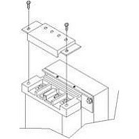
Connect Input/Output Power
The UPS should arrive with the bypass hardwire
box attached. If the box needs to be exchanged for
an optional model, remove and install the desired
box using the three captive screws marked in the
illustration at right.
To remove:
Loosen the screws about 20 turns until the box
can be pulled away from the UPS.
To install:
Align the connectors on the box and UPS. Push
the box into place. While holding the box firmly
against the UPS, tighten the three captive screws
until the box is secure. Do not over tighten.
Distribution Box Electrical Connections
Electrical connections are made through a remov-
able power distribution box that attaches to the rear of the UPS.
The installer must provide a 32A branch circuit breaker. The Input circuit breaker on the distribution
box and the Output circuit breaker on the rear fixed-panel of the UPS disconnect all power between
the main cabinet and the distribution box.
Models equipped with a manual bypass switch pass bypass power directly to the bypass switch from
the input terminal block. The input circuit breaker on the distribution box does not disconnect power
from the manual bypass switch.
Remove these screws
to release connector
15
Unscrew
these
captive
screws
Installation and Configuration
Related parts for IP20
Image
Part Number
Description
Manufacturer
Datasheet
Request
R

Part Number:
Description:
Encapsulated/PC Board Transformer
Manufacturer:
SOLA HEVI DUTY
Datasheet:

Part Number:
Description:
Linear & Switching Power Supplies 250W 24V @ 10A
Manufacturer:
SOLA HEVI DUTY
Datasheet:

Part Number:
Description:
Surge Suppressors DIN Rail Sgl Pair TVSS 36V
Manufacturer:
SOLA HEVI DUTY
Datasheet:

Part Number:
Description:
Surge Suppressors Cat 5/6 POE mal-fem
Manufacturer:
SOLA HEVI DUTY
Datasheet:
Part Number:
Description:
Surge Suppressors 2 Pair data/signa l Protection36V
Manufacturer:
SOLA HEVI DUTY
Datasheet:
Part Number:
Description:
Surge Suppressors Cat 5/6 POE fem-fem
Manufacturer:
SOLA HEVI DUTY
Datasheet:

Part Number:
Description:
Surge Suppressors Base Connector STC-642 Series
Manufacturer:
SOLA HEVI DUTY
Datasheet:
Part Number:
Description:
Surge Suppressors CCTV Coax surge protection
Manufacturer:
SOLA HEVI DUTY
Datasheet:
Part Number:
Description:
Surge Suppressors CCTV Coax surge protection Isolated
Manufacturer:
SOLA HEVI DUTY
Datasheet:
Part Number:
Description:
Surge Suppressors DIN Rail Sgl Pair TVSS 22V
Manufacturer:
SOLA HEVI DUTY
Datasheet:

Part Number:
Description:
Surge Suppressors DIN Rail Sgl Pair TVSS 60V
Manufacturer:
SOLA HEVI DUTY

Part Number:
Description:
Surge Suppressors RJ-11 Telephone Surge Protection
Manufacturer:
SOLA HEVI DUTY
Datasheet:
Part Number:
Description:
Surge Suppressors 2 Pair data/signal Protection20V
Manufacturer:
SOLA HEVI DUTY
Datasheet:
Part Number:
Description:
Surge Suppressors DIN RAIL Kit PCB1B base
Manufacturer:
SOLA HEVI DUTY
Datasheet: