IP20 SOLA HEVI DUTY, IP20 Datasheet - Page 24
IP20
Manufacturer Part Number
IP20
Description
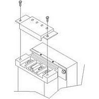
Fuse Cover Kit
Manufacturer
SOLA HEVI DUTY
Datasheet
1.RELAY_CARD-INT.pdf
(46 pages)
Specifications of IP20
Peak Reflow Compatible (260 C)
No
Kit Contents
2 Covers And Thread Forming Screws
Leaded Process Compatible
No
For Use With
SBE Fuse Block
Lead Free Status / RoHS Status
Lead free / RoHS Compliant
Available stocks
Company
Part Number
Manufacturer
Quantity
Price

Part Number:
IP2000-06
Manufacturer:
IR
Quantity:
20 000
Company:
Part Number:
IP2001
Manufacturer:
International Rectifier
Quantity:
10 000
Part Number:
IP2001
Manufacturer:
IR
Quantity:
20 000
Company:
Part Number:
IP2001PBF
Manufacturer:
International Rectifier
Quantity:
10 000
Company:
Part Number:
IP2001TR
Manufacturer:
IR
Quantity:
1 000
Company:
Part Number:
IP2001TR
Manufacturer:
International Rectifier
Quantity:
10 000
Part Number:
IP2001TR
Manufacturer:
IR
Quantity:
20 000
Company:
Part Number:
IP2001TRPBF
Manufacturer:
International Rectifier
Quantity:
10 000
Company:
Part Number:
IP2002
Manufacturer:
International Rectifier
Quantity:
10 000
Part Number:
IP2003
Manufacturer:
IR
Quantity:
20 000
Part Number:
IP2003AP
Manufacturer:
IR
Quantity:
20 000


7.0
7.1
7.1.1
C
The final step of installation may require custom configuration of your UPS using the enclosed config-
uration program. Some configuration settings may be changed only while the UPS is off. These should
be set before the UPS is put into full-time service powering the critical load.
For most users operating with 230VAC and with no external batteries, the factory default settings
will be adequate.
S4K5U6000-5 and S4K5U4500-5 Configuration Program Features
What You Will Need
In addition to the S4K5U UPS, you will need the configuration program diskette and serial cable
(beige or tan, 3-wire: GND, TX, RX; straight through 2-2, 3-3, 5-5) included in the UPS accessory box.
A Windows 95® or later computer, desktop or laptop, is also required to set up and run the configura-
tion program.
• Select one of three L-N output voltages to match local voltages.
• Enable/Disable Auto-Restart.
• Select frequency converter operation with a fixed output frequency of 50 or 60 Hz.
• Set the Low Battery Warning alarm time from 2 to 30 minutes.
• Enable/Disable the Auto-Battery test.
• Set the Auto-Battery test to 7, 14, 21, or 28 days.
• Specify the number of external battery cabinets connected to the UPS to adjust the remaining run
• Modify the shutdown setting of DB-9 pin 6 (for information on pin assignments, see Table 2).
ONFIGURATION
time calculations reported by Sola/Hevi-Duty software products.
P
ROGRAM
18
Configuration Program
Related parts for IP20
Image
Part Number
Description
Manufacturer
Datasheet
Request
R

Part Number:
Description:
Encapsulated/PC Board Transformer
Manufacturer:
SOLA HEVI DUTY
Datasheet:

Part Number:
Description:
Linear & Switching Power Supplies 250W 24V @ 10A
Manufacturer:
SOLA HEVI DUTY
Datasheet:

Part Number:
Description:
Surge Suppressors DIN Rail Sgl Pair TVSS 36V
Manufacturer:
SOLA HEVI DUTY
Datasheet:

Part Number:
Description:
Surge Suppressors Cat 5/6 POE mal-fem
Manufacturer:
SOLA HEVI DUTY
Datasheet:
Part Number:
Description:
Surge Suppressors 2 Pair data/signa l Protection36V
Manufacturer:
SOLA HEVI DUTY
Datasheet:
Part Number:
Description:
Surge Suppressors Cat 5/6 POE fem-fem
Manufacturer:
SOLA HEVI DUTY
Datasheet:

Part Number:
Description:
Surge Suppressors Base Connector STC-642 Series
Manufacturer:
SOLA HEVI DUTY
Datasheet:
Part Number:
Description:
Surge Suppressors CCTV Coax surge protection
Manufacturer:
SOLA HEVI DUTY
Datasheet:
Part Number:
Description:
Surge Suppressors CCTV Coax surge protection Isolated
Manufacturer:
SOLA HEVI DUTY
Datasheet:
Part Number:
Description:
Surge Suppressors DIN Rail Sgl Pair TVSS 22V
Manufacturer:
SOLA HEVI DUTY
Datasheet:

Part Number:
Description:
Surge Suppressors DIN Rail Sgl Pair TVSS 60V
Manufacturer:
SOLA HEVI DUTY

Part Number:
Description:
Surge Suppressors RJ-11 Telephone Surge Protection
Manufacturer:
SOLA HEVI DUTY
Datasheet:
Part Number:
Description:
Surge Suppressors 2 Pair data/signal Protection20V
Manufacturer:
SOLA HEVI DUTY
Datasheet:
Part Number:
Description:
Surge Suppressors DIN RAIL Kit PCB1B base
Manufacturer:
SOLA HEVI DUTY
Datasheet: