IP20 SOLA HEVI DUTY, IP20 Datasheet - Page 23
IP20
Manufacturer Part Number
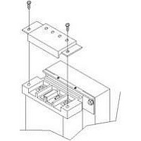
IP20
Description
Fuse Cover Kit
Manufacturer
SOLA HEVI DUTY
Datasheet
1.RELAY_CARD-INT.pdf
(46 pages)
Specifications of IP20
Peak Reflow Compatible (260 C)
No
Kit Contents
2 Covers And Thread Forming Screws
Leaded Process Compatible
No
For Use With
SBE Fuse Block
Lead Free Status / RoHS Status
Lead free / RoHS Compliant
Available stocks
Company
Part Number
Manufacturer
Quantity
Price

Part Number:
IP2000-06
Manufacturer:
IR
Quantity:
20 000
Company:
Part Number:
IP2001
Manufacturer:
International Rectifier
Quantity:
10 000
Part Number:
IP2001
Manufacturer:
IR
Quantity:
20 000
Company:
Part Number:
IP2001PBF
Manufacturer:
International Rectifier
Quantity:
10 000
Company:
Part Number:
IP2001TR
Manufacturer:
IR
Quantity:
1 000
Company:
Part Number:
IP2001TR
Manufacturer:
International Rectifier
Quantity:
10 000
Part Number:
IP2001TR
Manufacturer:
IR
Quantity:
20 000
Company:
Part Number:
IP2001TRPBF
Manufacturer:
International Rectifier
Quantity:
10 000
Company:
Part Number:
IP2002
Manufacturer:
International Rectifier
Quantity:
10 000
Part Number:
IP2003
Manufacturer:
IR
Quantity:
20 000
Part Number:
IP2003AP
Manufacturer:
IR
Quantity:
20 000


6.0
I
1. Verify that the Input Output circuit breakers are off.
2. During initial system checks, disconnect all loads (open load disconnects).
3. Inspect all wiring, cables, and connection.
4. If external battery cabinets are used, verify that the battery interconnect cables are fully inserted
5. If you are using a distribution box that includes a Manual Bypass Switch, place the switch in
6. Turn on the branch circuit disconnect to apply voltage to the input terminal block.
7. Using a voltmeter, verify the expected L1-N voltage.
8. After verifying proper input voltage to the UPS terminal block, turn off the branch circuit power,
9. Close the Input circuit breaker located on the distribution box. The green AC INPUT lamp should
10. Press the ON button for 1 second. The BYPASS lamp will light for several seconds before the UPS
11. Close the Output circuit breaker on the rear of the UPS. If a Manual Bypass Switch is used, the
12. Perform a Manual Battery Test - Press the ON button for 1 second. The front BATTERY lamp will
13. Review all setting option provided by the configuration program. Some changes require that the
14. Connect all loads for normal operation.
NITIAL
in the sockets.
BYPASS position.
If no Manual Bypass Switch is used, there will be no output voltage at this time. If a Manual
Bypass Switch is used, verify that the same voltages appear at the Output terminals. If a Manual
Bypass Switch is used, the Bypass lamp will light by the switch. If no manual bypass switch is
used, there will be no output voltage at this time.
close all access panels to the distribution box, and reapply input power.
illuminate on the front panel.
ON lamp turn on continuously. If the batteries are determined to charged above 80%, an
automatic battery test will run for about 15 seconds.
Inverter lamp by the switch will light. If a Manual Bypass Switch is used, transfer the switch to
the Inverter position. The output terminal block will be powered at this time.
light for about 15 seconds and then return to only the UPS ON and AC INPUT lamps being on.
UPS be OFF. If this is the case, these should be programmed before powering the loads. The
configuration program is described in the next section.
S
TART
-U
P AND
E
LECTRICAL
17
C
HECKS
Initial Start-Up and Electrical Checks
Related parts for IP20
Image
Part Number
Description
Manufacturer
Datasheet
Request
R

Part Number:
Description:
Encapsulated/PC Board Transformer
Manufacturer:
SOLA HEVI DUTY
Datasheet:

Part Number:
Description:
Linear & Switching Power Supplies 250W 24V @ 10A
Manufacturer:
SOLA HEVI DUTY
Datasheet:

Part Number:
Description:
Surge Suppressors DIN Rail Sgl Pair TVSS 36V
Manufacturer:
SOLA HEVI DUTY
Datasheet:

Part Number:
Description:
Surge Suppressors Cat 5/6 POE mal-fem
Manufacturer:
SOLA HEVI DUTY
Datasheet:
Part Number:
Description:
Surge Suppressors 2 Pair data/signa l Protection36V
Manufacturer:
SOLA HEVI DUTY
Datasheet:
Part Number:
Description:
Surge Suppressors Cat 5/6 POE fem-fem
Manufacturer:
SOLA HEVI DUTY
Datasheet:

Part Number:
Description:
Surge Suppressors Base Connector STC-642 Series
Manufacturer:
SOLA HEVI DUTY
Datasheet:
Part Number:
Description:
Surge Suppressors CCTV Coax surge protection
Manufacturer:
SOLA HEVI DUTY
Datasheet:
Part Number:
Description:
Surge Suppressors CCTV Coax surge protection Isolated
Manufacturer:
SOLA HEVI DUTY
Datasheet:
Part Number:
Description:
Surge Suppressors DIN Rail Sgl Pair TVSS 22V
Manufacturer:
SOLA HEVI DUTY
Datasheet:

Part Number:
Description:
Surge Suppressors DIN Rail Sgl Pair TVSS 60V
Manufacturer:
SOLA HEVI DUTY

Part Number:
Description:
Surge Suppressors RJ-11 Telephone Surge Protection
Manufacturer:
SOLA HEVI DUTY
Datasheet:
Part Number:
Description:
Surge Suppressors 2 Pair data/signal Protection20V
Manufacturer:
SOLA HEVI DUTY
Datasheet:
Part Number:
Description:
Surge Suppressors DIN RAIL Kit PCB1B base
Manufacturer:
SOLA HEVI DUTY
Datasheet: