17 26 220 2101 HARTING, 17 26 220 2101 Datasheet - Page 52
17 26 220 2101
Manufacturer Part Number
17 26 220 2101
Description
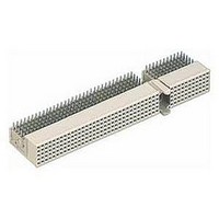
HARD METRIC CONNECTOR, RECEPTACLE 220POS
Manufacturer
HARTING
Series
Har-bus HMr
Datasheet
1.17_33_000_4102.pdf
(56 pages)
Specifications of 17 26 220 2101
Row Pitch
2mm
Pitch Spacing
2mm
No. Of Contacts
220
Gender
Receptacle
Contact Termination
Right Angle Press Fit
No. Of Rows
5
Connector Type
Hard Metric (HM)
Lead Free Status / RoHS Status
Lead free / RoHS Compliant


Recommended accessories: hexagon nut ISO 4032-M3-8
Identification
Guide pin
Receptacle for guide pin
Dimensions [mm]
Guide pin
Receptacle
for guide pin
Board drillings
(View-X)
1)
2)
3)
4)
Non-metallised drillings
No tracks, except solder eyes
Limit area of components (valid for both pcb sides)
Recommended board drilling is 3.5 (-0.05) mm
serrated lock washer DIN 6798-A-3.2 FSt
Guiding system
The guide pin solution from HARTING
allows
extreme conditions. This might be large
and heavy boards that bow under their own
weight. Also insufficiently aligned or worn
out rack systems can be tolerated better
with the use of HARTING's guiding system,
which also reduces the potential danger
of damaging cards when being forced into
flexing racks.
The guide pin and receptacle's design
solution allows to overcome a 3 mm [.118']
offset between the backplane and the
mating daughtercard. The reducing diameter
of the pin (from 4.85 mm to 3.4 mm)
ensures that its positioning task is smoothly
transferred to the connectors as soon
as they start to engage. Finally the thin
diameter section of the guide pin is no
longer positioned by the ferrule of the
receptacle, ensuring that the pin is able to
freely follow any movement imposed by the
engaging connector. This ensures that there
is no static stress between the connectors
and the guiding system.
The rugged metal designed guide pin is
screwed to the backplane with standard
hexagon screws. Whereas the molded
receptacle is designed with four press-
in pegs that can be installed to the board
together with the connectors.
The tooling can be ordered with the part
numbers 07 79 000 0157 (top tool) and
07 79 000 0158 (bottom tool).
17 79 000 0080
07 73 000 0280
Part number
safe
mating
under
sometimes
11
51
Related parts for 17 26 220 2101
Image
Part Number
Description
Manufacturer
Datasheet
Request
R

Part Number:
Description:
HARD METRIC CONNECTOR, RECEPTACLE 220POS
Manufacturer:
HARTING
Datasheet:

Part Number:
Description:
Har-bus HM Fe. T. Monobl. 47 M. Schir.
Manufacturer:
HARTING

Part Number:
Description:
17 CIR MTA-100 ASSY TAPE LF
Manufacturer:
Tyco Electronics
Datasheet:
Part Number:
Description:
17 AMPMODU MT ASSY SR.100CL SN
Manufacturer:
Tyco Electronics
Datasheet:
Part Number:
Description:
17 CIR MTA-100 CONN BLUE LF
Manufacturer:
Tyco Electronics
Datasheet:

Part Number:
Description:
Standard LED - SMD Hyper Red
Manufacturer:
Everlight Electronics CO., LTD
Datasheet:
Part Number:
Description:
Standard LED - SMD Brilliant Green
Manufacturer:
Everlight Electronics CO., LTD

Part Number:
Description:
Standard LED - SMD Red, 624nm 60mcd, 20mA
Manufacturer:
Everlight Electronics CO., LTD
Datasheet:
Part Number:
Description:
Manufacturer:
Everlight Electronics CO., LTD
Datasheet:
Part Number:
Description:
EVL17-21SYGC/S530-E2/TR8 TOP VIEW, GREEN
Manufacturer:
Everlight Electronics CO., LTD
Datasheet:
Part Number:
Description:
Manufacturer:
Everlight Electronics CO., LTD
Datasheet:

Part Number:
Description:
LED SUPER YELLOW WATER CLR 0805
Manufacturer:
Everlight Electronics Co Ltd
Datasheet:
Part Number:
Description:
LED INGAN BLUE WATER CLEAR 0805
Manufacturer:
Everlight Electronics Co Ltd
Datasheet:
Part Number:
Description:
LED BRILLIANT GREEN CLEAR 0805
Manufacturer:
Everlight Electronics Co Ltd
Datasheet: