COBOX-FL-11 Lantronix, COBOX-FL-11 Datasheet
COBOX-FL-11
Specifications of COBOX-FL-11


Related parts for COBOX-FL-11


COBOX-FL-11 Summary of contents
Page 1
... CoBox-FL/CoBox-FL-IAP User Guide Part Number 900-285 Revision E 8/03 ...
Page 2
... Copyright and Trademark © 2003, Lantronix. All rights reserved. No part of the contents of this book may be transmitted or reproduced in any form or by any means without the written permission of Lantronix. Printed in the United States of America. Ethernet is a trademark of XEROX Corporation. UNIX is a registered trademark of The Open Group ...
Page 3
... The information in this guide may change without notice. The manufacturer assumes no responsibility for any errors which may appear in this guide. Date Rev. Comments 07/01/01 C Current release. 09/25/02 D Revised for Device Installer, new format. Includes all CoBox-FL devices. 08/25/03 E Updated warranty information. ...
Page 4
... ISO/IEC Guide 22 and BS 7514) Manufacturer’s Name & Address: Lantronix, 15353 Barranca Parkway, Irvine, CA 92618 USA Declares that the following product: Product Name Model: CoBox-FL/CoBox-FL-IAP Device Server Conforms to the following standards or other normative documents: Safety: EN60950:1992+A1, A2, A3, A4,A11 Electromagnetic Emissions: ...
Page 5
... Material Authorization (RMA) will be issued. Following receipt of a RMA number, the customer shall return the product to Lantronix, freight prepaid. Upon verification of warranty, Lantronix will -- at its option -- repair or replace the product and return it to the customer freight prepaid. No services are handled at the customer's site under this warranty. This warranty is voided if the customer uses the product in an unauthorized or improper way environment for which it was not designed ...
Page 6
... Fax: +49 (0) 1688 ursula.koch@lantronix.com Asia Pacific 16th Floor Cheung Kong Center 2 Queen's Road Central Hong Kong Tel: +852 2297 2287 Fax: +852 2297 2357 asiapacsales@lantronix.com EMEA Sales (Europe, Mid East, Africa) eu_sales@lantronix.com eu_order@lantronix.com EMEA Technical Support +49 (0) 7720 3016 20/57 eu_techsupp@lantronix.com ...
Page 7
... Table of Contents 1. Introduction...................................................................................................................... 1-1 1.1 CoBox-FL ........................................................................................................... 1-1 1.2 CoBox-FL-IAP Device Server............................................................................ 1-2 1.2.1 Industrial Automation Protocols ......................................................... 1-3 1.3 Network Protocols .............................................................................................. 1-4 1.3.1 Packing Algorithm.............................................................................. 1-4 1.3.2 IP Address........................................................................................... 1-4 1.3.3 Port Number........................................................................................ 1-4 1.4 Serial Interface.................................................................................................... 1-5 1.4.1 Channel 1 ............................................................................................ 1-5 1.4.2 Channel 2 ............................................................................................ 1-6 1 ...
Page 8
... Flush Mode (Buffer Flushing)...........................................................3-21 3.6.10 Pack Control ....................................................................................3-22 3.6.11 DisConnTime (Inactivity Timeout).................................................3-23 3.6.12 Send Characters...............................................................................3-23 3.6.13 Telnet Terminal Type......................................................................3-23 3.6.14 Channel (Port) Password .................................................................3-23 3.7 Expert Settings ..................................................................................................3-24 3.7.1 TCP Keepalive time in s....................................................................3-24 ii CoBox-FL User Guide ...
Page 9
... UDP Datagrams .................................................................................................. 8-1 8.2 Configuring Multiple Devices ............................................................................ 8-3 8.2.1 Acquiring a Valid Setup Record ......................................................... 8-3 8.2.2 Sending a Setup Record ...................................................................... 8-4 8.2.3 The Intel Hex Format.......................................................................... 8-5 8.2.4 Calculating the Checksum .................................................................. 8-6 8.2.5 Calculating the Two’s Complement ................................................... 8-6 CoBox-FL User Guide Contents iii ...
Page 10
... IP Addresses..................................................................................................................10-1 10.1 Class A Network .............................................................................................10-1 10.2 Class B Network..............................................................................................10-1 10.3 Class C Network..............................................................................................10-1 10.4 Network Address.............................................................................................10-2 10.5 Broadcast Address ...........................................................................................10-2 10.6 IP Netmask ......................................................................................................10-2 10.7 Private IP Networks and the Internet...............................................................10-3 10.8 Network RFCs.................................................................................................10-3 11. Glossary.........................................................................................................................11-1 iv CoBox-FL User Guide ...
Page 11
... List of Figures Figure 1 – CoBox-FL-IAP ..................................................................................................... 1-2 Figure 2 - RJ-45 Connector.................................................................................................... 1-7 Figure 3 – CoBox-FL Connected to Serial Device and Network .......................................... 2-2 Figure 4 – CD Main Window ................................................................................................ 2-5 Figure 5 - DeviceInstaller Window........................................................................................ 2-6 Figure 6 - Assign IP Address Window .................................................................................. 2-6 Figure 7 - Ping Device Window ............................................................................................ 2-7 Figure 8 - Search Network Window ...................................................................................... 2-8 Figure 9 - Devices in a Group ...
Page 12
... Contents List of Tables Table 1 - Ethernet Interface Signals .......................................................................................1-7 Table 2 - CoBox-FL LED Functions.....................................................................................1-9 Table 3 - Technical Specs.....................................................................................................1-12 Table 4 - Standard IP Network Netmasks ............................................................................3-13 Table 5 - Netmask Examples................................................................................................3-13 Table 6 - Interface Mode Options ........................................................................................3-15 Table 7 - Common Interface Mode Settings ........................................................................3-16 Table 8 - Flow Control Options............................................................................................3-16 Table 9 - Connect Mode Options ...
Page 13
... Table 38 - Disconnect Mode Options .................................................................................... 9-5 Table 39 - Flush Mode Options ............................................................................................. 9-7 Table 40 - Interface Mode Options ...................................................................................... 9-13 Table 41 - Pack Control Options ......................................................................................... 9-14 CoBox-FL User Guide Contents vii ...
Page 14
...
Page 15
... This manual describes the CoBox-FL family of Device Servers, including the CoBox-FL Device Server and the CoBox-FL-IAP Device Server with Industrial Automation Protocols. Most of the material in this manual applies to all of the CoBox-FL products. However, in some cases there will be some features that apply to only one product. In those cases, a note will explain the variation ...
Page 16
... Device Servers in the IAP family. Figure 1 – CoBox-FL-IAP Lantronix provides IAP Device Servers specifically designed for different industrial environments. • CoBox-DR1-IAP, with a DIN rail interface for harsh environments or alongside controls instruments in electrical panels. • CoBox-FL-IAP, with fiber connectivity for long cable runs or electrically hazardous environments. ...
Page 17
... The CD that comes with your Device Server includes DeviceInstaller, a Windows based configuration software that simplifies the process of installing protocols and configuring them for use with attached devices. IAP Device Servers use Flash memory for maintenance-free, non-volatile storage which allows for fast system upgrades. CoBox-FL User Guide Introduction 1-3 ...
Page 18
... More than one Telnet connection can be established to one host using the Telnet port; however, the other peer IP address/port number combinations must be different. In the CoBox-FL, a port number can be configured on the channel (port). The CoBox-FL uses this port number for outgoing messages and incoming connections, or UDP datagrams, which are addressed to its port number ...
Page 19
... Serial Interface The CoBox-FL has two serial ports uses a DB-25F (DCE) connector and supports RS- 232, RS-422/485 uses a DB-9 connector and supports RS-232 only. It supports 10Mb/s Ethernet through the RJ-45 (10BASE-T) connector or the ST-Fiber (10BASE-FL). It can be configured via HTTP, SNMP, DHCP or Telnet. It contains a Flash ROM for easy software upgrades ...
Page 20
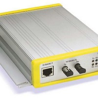
... RXA(in) DCDA (in 1.5 RJ-45 Ethernet Interface The CoBox-FL’s back panel contains a 9-30V AC/DC power plug, four LEDs, an ST-Fiber (10BASE-FL) Ethernet port, and an RJ-45 (10BASE-T) Ethernet port. Both Ethernet ports support 10 Mbps and are auto detecting. 10BASE-T Ethernet Port Note: Do not attempt to connect both Ethernet ports simultaneously. If one is used, the other is disabled ...
Page 21
... RX RX 1.7 ST-Fiber Ethernet Connectors Rx Tx The CoBox-FL also supports 10Mbit Ethernet through an ST-Fiber Ethernet connector. Note: Do not attempt to connect both Ethernet ports simultaneously. If one is used, the other is disabled. CoBox-FL User Guide 1 Ethernet (RJ45) View from Connector End Primary Function Transmit Data + ...
Page 22
... Introduction 1 .8 Serial In terface Cable The CoBox-FL can be conn ected to a seria T he serial device can be RS -232 or RS-485/422. The following diagram shows a typica i nterface cable for the RS 32 Serial interface. The UDS-M-SBC is an optional male -2 to RS-485 screw block con nector ...
Page 23
... Simultaneously lit red and green LEDs means something is wrong. If the red LED is lit or blinking, count the number of times the green LED blinks betwee indicate which fault condition exists. The following table explains serial LEDs. LEDs Table 2 - CoBox-FL LED Functions LED Meaning GREEN Lights solid green to indica ...
Page 24
... Introduction 1.11 Dimensions The CoBox-FL dimensions are shown in the following drawing. Note: For CoBox-FL and CoBox-FL-IAP. 4.46 in. (11.34 cm 1.39 in. (3.55 cm) 1.12 Product Information Label The product information label contains important information about your specific unit. S/N:5226863 COBOX-FL-IAP 00-20-4A-52-68-EF Rev. A11 Made in USA 1 ...
Page 25
... Power Requirements The CoBox-FL is shipped with a 12VDC, 0.8A, 100-240VAC, 50-60Hz power supply, but any power supply between 9 VAC/DC and 30V AC/DC can be used. CoBox-FL User Guide 9-30V AC/DC Power Introduction 1-11 ...
Page 26
... Telnet login System Software Windows® 95/98/ME/NT/2000 based configuration software LEDs Network Transmit, Network Receive, Good Link, Collisions, Channel 1 Status, Channel 2 Status, Diagnostic Compatibility Ethernet: Version 2.0/IEEE 802.3 1-12 L, and CoBox-FL-IAP), Modbus (CoBox- 22/485 (DCE pinout) out) 300bps to 115Kbps CoBox-FL User Guide ...
Page 27
... Protocol manuals are found on the software CD. This section describes the setup and configuration dialogs for the Standard Tunnel Protocol. Note: The following information is based on the condition that a CoBox-FL is loaded with Standard Tunnel Protocol. The CoBox-FL-IAP with IAP Standard Tunnel Protocol may have different options available. ...
Page 28
... Setup (configuration) Mode window. 2.2 Physically Connecting the Unit The following diagram shows a typical hardware configuration for the CoBox-FL. Use one of the cables described in Serial Interface Cable on page 1-8 to connect a PC COM port to the CoBox-FL. ...
Page 29
... IP address. Obtain the following information before starting to set up your unit: IP Address: ___ ___ ___ ___ Subnet Mask: ___ ___ ___ ___ Gateway: ___ ___ ___ ___ CoBox-FL User Guide DHCP on page 2-4. ARP and Telnet AutoIP on page 2-4. Getting Started on page 2-11. ...
Page 30
... The unit ships with a default IP address of 0.0.0.0, which automatically enables DHCP. Provided a DHCP server exists on the network, it will assign the unit an IP address, gateway address, and subnet mask when the unit boots up. The CoBox-FL has acquired an IP address if the red LED stops flashing and the green ...
Page 31
... Enter your CD drive letter, colon, backslash, deviceinstaller.exe (e.g., E:\deviceinstaller.exe). Figure 4 – CD Main Window 2. Click the Device Installer button. The installation wizard window displays. 3. Respond to the installation wizard prompts. (When prompted to select an installation type, select Typical.) CoBox-FL User Guide Getting Started 2-5 ...
Page 32
... Figure 5 - DeviceInstaller Window 1. Click the IP icon . T he Assign IP Address window displa Figure 6 - Assign IP Address Window 2. In the Enter the Hardware or Ethernet Address field, enter the Ethernet address (MAC address), which is listed on the label on the side of the unit. 2-6 ys. CoBox-FL User Guide ...
Page 33
... IP address segment you are working with. If you are not sure, check with your systems administrator. 3. Click the Back button to retu CoBox-FL User Guide y in the window, indicating that the IP , make sure the unit is properly assigned is valid for the particular network rn to the Device Installer window ...
Page 34
... Click the Search the network for devices displays. Figure 8 - Search Network Window 2. Select the PC Network Cla the Start Search button. A list of all active units displays Clic k the Save button. A confirmation message displays. 5. Click OK . 2-8 icon Search Network window ss. Class C is the default. CoBox-FL User Guide ...
Page 35
... Devices in a Group Now you can manage (configure) the unit so that it works with the serial device on the netw ork. CoBox-FL User Guide turn to the DeviceInstaller window. The DeviceInstaller devices in the group, including the unit you are setting up. Getting Started 2-9 ...
Page 36
... The Set Configuration icon sends a saved file to the unit. To Get Configuration information see Get Configuration on page 3-26. To Set Configuration of a specific device see Set Configuration on page 3-27. 2-10 . The Device Management window displays CoBox-FL User Guide ...
Page 37
... ARP and Telnet The unit’s IP address must be configured before a network connection is available. You are able to ARP an address into a CoBox/UDS device even if there is already an address in the unit. If the unit has no IP address, you can use Address Resolution Protocol (ARP) method from UNIX and Windows-based systems to assign a temporary IP address ...
Page 38
... Note: The easiest way to enter Setup M emulation) while powering up the unit this point, the screen display is the same as when you use a Telnet connectio continue with a serial port login Using a Telnet Connection on page 3-1 2-12 ode is to hol d down the x key at the terminal ( CoBox-FL User Guide ...
Page 39
... Open your JAVA enabled web browser and enter the IP address. The Lantronix Web Manager page will display Web Manager Page for a summary of the menu selections. Note: The CoBox-FL-IAP may not have a web page or may use a different format web page. CoBox-FL User Guide ...
Page 40
... IP address (see Methods of Assigning the IP Address), you can log into it usin g a standard Web browser that is Java enabled. Type the unit's IP address into the Web browser's URL (Address/Location) field. 3-2 . The Search to open the Device Management elections. CoBox-FL User Guide a ...
Page 41
... To Get device configuration information see Get Confi Configuration information can be read from a device and saved 8. To Set the configurati specific device see Set Configuration on page 3-27 A device can be configured by reading a configuration file and sending the information to the device. CoBox-FL User Guide Configure guration on page 3-26 file. 3-3 ...
Page 42
... Configure 3.3 Web Manager Page Note: The CoBox-FL-IAP may not have a web page or may use a different format web page. You can start a web browser for configuration by opening your JAVA enabled web browser and entering the IP address or by clicking the Web Configuration Management window ...
Page 43
... Click the Unit Configuration button to display the following dialog box. This page contain the Server Configuration and the Port Configuration settings. These are static settings read from the device. Note: The following screen shots represent the web page shown wh with cbxw300.cob firmware. CoBox-FL User Guide Configure s en the device is loaded 3-5 ...
Page 44
... Mode via a Telnet connection to port 9999. The password is limited to 4 characters. (An enhanced password setting of 16 characters is available under Security Settings on the Tel Setup Mode window.) Note: No password is required to access the Setup Mode window via a serial connection. 3-6 s will require you to enter the net CoBox-FL User Guide ...
Page 45
... Startup: No active startup, with any character, with active DTR (Inactive), with CR (0x0D) only, Manual Connection, Autostart, Modem Mode Remote IP Address: (user selectable) Remote Port: (user selectable) Local Port: 10001 (default 10001, user selectable) CoBox-FL User Guide , 57600, 115200 acters to Host, CTS/RTS Configure 3-7 ...
Page 46
... Idle Time: Force transmit 12 ms, Force transmit 52 ms, Force Transmit 250 ms, Force Transmit 5000 ms Trailing Characters: None, One, Two Send Immediate After Sendchars: Enable, Disable Send Define2-Byte Sequence: Enable, Disable Send Character 01: (User Selectable) Send Character 02: (User Selectable) 3-8 CoBox-FL User Guide ...
Page 47
... Update Se ttings C lick the Update Se ttings button to send all changed settings to the device. CoBox-FL User Guide na ble, Disable ntronix Tech Support web page, the FTP-Site button r downloading new firmware, manuals, and other files. The u to the Contact Information page. Configure ons ...
Page 48
... Enter. 7. When you are finished, save the new configurations (option 9). The unit will reboot. 3-10 g command, where nfiguration port number. p Mode seconds. The configuration ode Window. (Firmware Code: AQ) pe the value and press Enter confirm a current ? CoBox-FL User Guide ...
Page 49
... Expert ******************* TCP Keepalive : 0s Change Setup :0 Server configuratio 1 Channel 1 configuration 5 Expe 6 Secu 7 Factory defaults 8 Exit without save 9 Save and exit Figure 13 - Setup Mode Window CoBox-FL User Guide enabled (not IAP firmware) (not IAP firmware) enabled enabled enabled enabled disabled el 1 ***************** 4C, Flow 00 ...
Page 50
... L ED starts bli nking. You have one second to .(000) .(000 ) ation about IP addressing. s communication to other LAN segments. The gateway ram to your unit's parity , 1 stop bit ter power-up, minal ( -10. (00) Methods of Assigning the CoBox-FL User Guide ...
Page 51
... CoBox-FL User Guide host bits to be entered, then calculates the netmask, which w th ave d p ara me Netm sk a 255.0.0.0 255.255.0.0 255.2 5.255.0 5 Configure host ters are disp lay ed (for 3-13 ...
Page 52
... YY is what you chose for the last octet of the IP address. If the IP address you specify 0.0.0.12, then the DHCP name will be LTX12. This method will only work with 2 digit numbers (0-99). 3-14 under Security Settings for Telnet ese products. to CXXXXXX (XXXXXX is the last 6 digits of the he DHCP name will be LTXYY where CoBox-FL User Guide ia ge the is ...
Page 53
... Odd Parity 1 Stop bit Stop bit 1 1 (1) The CoBox-FL requires you to choose the correct setting in the IF mode, and to also set the front-panel switch for selection of RS-232/RS-485. CoBox-FL User Guide ion (Serial Port Parameters) es are 300, 600, 1200, 2400, 4800, 9600 (default), second. e. ...
Page 54
... RS-232C, 7-bit, Even Parity, 1 stop bit RS-485 2-Wire, 8-bit, No Parity, 1 stop bit RS-422, 8-bit, Odd Parity, 1 stop bit (1) The CoBox-FL requires you to choose the correct setting in the IF mode. 3.6.3 Flow Flow control sets the local handshake method for stopping serial input/output. ...
Page 55
... IP address already configured in the unit is 129.1.2.3, then an example command string would be C3/7. (This would connect to 129.1.2.3 and port 7.) You may also use a different ending for the connection string. For example, C50.1/23 would connect you to 129.1.50.1 and port 23. CoBox-FL User Guide ...
Page 56
... Datagram type. t modem interface to the e onnected to a remote ce m odems with device a ll, without havi ng to change , D6 (echo with full verbose), accept d CoBox-FL User Guide ...
Page 57
... Note: These AT commands are only recognized as single commands like ATE0 or ATV1; compound commands such as ATE0V1 are not recognized. All other AT commands with Modem Mode set to full verbose acknowledge with an OK, but no action is taken. CoBox-FL User Guide ined within the unit. unit. ...
Page 58
... When Ctrl D or Hex 04 are detected, the connection is dropped. Both Telnet mode and Disconnect with EOT must be for Disconnect with EOT to function properly. Ctrl D will only be detected going from the serial port to the network. 6. When DTR on the CoBox/UDS product transitions the serial port will drop. ...
Page 59
... Output Buffer (Network to Serial) Clear with a connection that is initiated from the UDS to the network Clear with a connection initiated from the network to the UDS Clear when the network connection to or from the UDS is disconnected Alternate Packing Algorithm (Pack Control) Enable CoBox-FL User Guide ...
Page 60
... Trailing Characters: In some applications, CRC, Checksum, or other trailing characters follow the end-of-sequence character; this option helps to adapt frame transmission to the frame boundary. 3- routed Wide Area Network (WAN). Adjusting are CoBox-FL User Guide ...
Page 61
... IBM hosts. 3.6.14 Channel (Port) Passw This param eter appears only if the channel ( Mode (see D onnMode on page 3- isC CoBox-FL User Guide ransmit condition (sendchar or timeout). line (for example, ETX, EOT, see Pack Control on page 3-22). ord po rt) p assword option is enabled in Disconnect 20) ...
Page 62
... Note: You can change these settings via Telnet or serial connections only, not on the Web- Manager. Note: The Expert Settings option does not appear with CoBox-FL-IAP. These parameters should only be changed if you are an expert and definitely know the consequences the changes might have. ...
Page 63
... Teln 3.9 Factory Defaults Select 7 to reset the unit’s Channel 1 and Enhanced Security to the factory default settings. The server configurations (IP address information) remain unchanged. CoBox-FL User Guide ex) www.lantronix.com. les remote configuration. You can ...
Page 64
... DeviceInstaller main window. In the Configuration File field, click the Open File button to select a filename for the configuration file. Click the Get button and the file information is read from the devic e and saved in the selected file. 3-26 ry. read and saved in ick the Get ears. CoBox-FL User Guide ...
Page 65
... DeviceInstaller main window. In the Configuration File field, click the Open File button to select a configuration file. Click the Set button and the file information is read and stored in the device. CoBox-FL User Guide can be saved in a file and later used to set the configuration Configure ...
Page 66
...
Page 67
... You can update the unit's internal operational code to a newer revision, or change the code to operate with a specific vendor. The CoBox-FL-IAP was designed to allow loading of vendor specific protocol firmware. This firmware takes the place of the IAP Standard Tunnel Protocol. Vendor specific protocol ...
Page 68
... DeviceInstaller to install it. 1. Download the updated firmware files from www.lantronix.com or ftp.lantronix.com and store them in a subfolder on your computer 2. Click the Start button on the Task Bar and select Programs\DeviceInstaller\Device Installer. The Device Instal Figure 14 - Device Instal ler 4-2 . ler window displays. CoBox-FL User Guide ...
Page 69
... Click the Back button to return to the Device Installer window. The Device Installer window now lists all of the devices in the g Fig ure 16 - Devices in a Group CoBox-FL User Guide . The Search Network window indow all active units on the local network displays. roup, including the unit you are updating. ...
Page 70
... Make sure the Put and Binary options at the top of the window are selected. 3. Enter the full path of the firmware file in the Source File field. 4-4 ype that is currently in the unit. ype currently installed or an error message the software CD or the file messages display in the lower CoBox-FL User Guide . The ...
Page 71
... In the Destination File field, enter the current the internal Web interface. (For CoBox- DF1. For CoBox-FL Stan 5. In the Remote Host field, enter the IP address of the unit being upgraded. 6. Click the Put button to transfe Fig ure 8 - TFTP Dialog Box 1 The ...
Page 72
... PC then open a DOS Window mputer via the unit ’s serial port page 7-1). Mo the unit using the DL comma n d. teg . e OM code to er while nonfunctional unit. . The downl oaded file rity of the firmware image The following message CoBox-FL User Guide ...
Page 73
... Everything is totally tra nsparent to the serial device, t • Redirects up to 255 CO M ports simultaneously over • Provides raw mode dat a only, which means it will not c • Supports Windows 2000, Windows NT4.0, and Windows • Easy to install and even easier to configure CoBox-FL User Guide ...
Page 74
... Task Bar and select Run b) Enter your CD drive letter, colon, backslash, devicec D:\devicecomm.exe). Figure 19 – UDS/CoBox Main Window 2. Click the DeviceComm Manager button. The installation wizard window displays. Respond to the installation wizard prompts. Note: DeviceComm Manager is installed in the Control Panel. ...
Page 75
... An active TCP/IP connection exists between the COM port and 3. Sele ct one of the DISABLED ports by clicking on it, and then press th 4. Select the Enabled check box. 5. Type in the IP address of the target device server in the “Host:” section. CoBox-FL User Guide DeviceComm Manager . the device server e Edit button. ...
Page 76
... You may also find the our W indows OS documentation for more de ra ox. example, all data sent to COM4 will be sent across ant not eout” and the “Write tails on CoBox-FL User Guide ...
Page 77
... Technical Support Europe, Middle East, and Africa +49 (0) 7 720 3016 20/57 eu_techs upp@lantronix .co m CoBox-FL User Guide cable) are secure. ight be caused by duplicate IP addresses on the network this chapter you are unable to fix dge base ...
Page 78
... Telnet to port ble u ed (please try to include information on rr the time problem) m ake sure th at the CoBox-FL is powered up Lin k LED is not lit, then the physical network sing a g ood network connection Solution ed-in user Have someone from your IT department log you in with sufficient rights ...
Page 79
... Call Lantronix Technical Support if the blinking pattern indicates a critical error. The serial settings for the serial device and the UDS/CoBox must match. The default serial settings for the UDS/CoBox are RS232, 9600 Baud, 8 Character Bits, No Parity, 1 Stop Bit, No Flow Control ...
Page 80
... Whe n connecting to the Web- Your computer is not able to Man ager within the connect to port 30718 (77FEh) UDS /CoBox, the message “No on the Connection With CoBox” displays. 6-4 Solution sequence that tells you this). If you do no the serial is not disabled. ...
Page 81
... Device Server with th IP address address is given, the c ommand is e xecuted locally. Note: All commands must be given in capital letters. CoBox-FL User Guide e e interface used for diagnostic purposes (see Table 17 - Mode without network connections. MAC address 00:20:4A:14:01:18 x.xxx ) ...
Page 82
... Server, where xxx.xxx.xxx.xxx is the IP address, and yyyy.yyy.yyyy.yyy is the two-part identification number at the bottom of the label, converted to decimal, and written twice. Exit diagnostics mode Gets a me mory page of configuration information from the device. Sets a memory page of configuration information on the device. CoBox-FL User Guide at ...
Page 83
... UDP packet. Notes These 2 bytes are used to prevent accidental reset of the Device Server. (Value fo r standard CoBox firmware [Hex ], 3Q) The Device Server responds with the F block below. ytes of the The first 16 bytes of the firmware image contain the software type (offset 4,5) and checksum (offset 14,15) ...
Page 84
... No reply is sent by the Device Server, which restarts using the new I block is received. e serial Example (all in Hex addre ss of the node with serial number 42-18 set t o 129.0.1.2 n/a set the IP address on the local P address after the CoBox-FL User Guide ...
Page 85
... At the prompt, enter GC followed by a carriage return. The Device Server will respond with its setup record in Intel Hex format. 4. Copy the setup record into a text file and save it for future use. CoBox-FL User Guide paste” or UDP (see Network Configuration using UDP tu ...
Page 86
... IP The Intel Hex Format on page 8-5). tagram to the Device Server (see Network Configuration evice Server responds with the F9 datagram, which a h ost PC via UDP. CoBox-FL User Guide ...
Page 87
... Hex) for address 0020 (32 decimal communication with the node, the following block types are defined: Table 20 - Block Types Option Data block program memory (firmware) End record Data block configuration memory CoBox-FL User Guide ork support enabled) on the master Device Server (see targ et ...
Page 88
... You can also calculate the two’s complement by subtracting the sum from 100. Using the example above again, 100 - E2 = 1E. It may help to use a scientific calculator. 8 cks two-digit lue from to 55 the line and taking the two’ lon eck um byte in the sum tored at 0030, 0031, and 0032 the number to reach a CoBox-FL User Guide ...
Page 89
... Number of host bits for subnetting matching standard netmask for Class used. 07 Reserved (0) 08-11 Telnet configuration password ( use ) 12-15 Gateway IP address (0,0,0,0 if not used) 16-63 48-byte Channel 1 parameters; param er setup Cha ne Channel Parameters) 64-111 48-byte Channel 2 parameters; parameter setup Channe Channel Parameters)) 112-119 Reserved (0) CoBox-FL User Guide (CoBo x only Table E-4: ...
Page 90
... Table 26 - Flow Control Options Table 27 - Connect Mode Options Table 28 - Disconnect Mode O s (00 if unused) Table 29 - Flush Mode Options Table 30 - Pack Control Options et terminal type optio n (15 characters max Disconnect Mod e is set, Telnet d. ed Socket Connection (Bit ) ) ) ) ptions ) sed Disconnect CoBox-FL User Guide ...
Page 91
... Even Parity Odd Parity 1 Stop bit 0 2 Stop bits 1 (1) The CoBox-FL requires you to choose the correct setting in the IF mode. The following tab le demonstrates how to build some common Interface Mode settings: Table 24 - Common Interface Mode Settings Option RS-232C, 8-bit, No Parity, 1 stop bit ...
Page 92
... Flow Control option s: Table 26 - Flow Control Options flo control OFF flow co ntro handsha ke w ith RTS/CTS lines OFF pass ch ara cters to host 8-10 19200 or less. Use the following table to Hex CoBox-FL User Guide ...
Page 93
... With active D TR With CR (0x0 D) only Man ual conne ction Auto sta rt Dat agram Dire cted UDP Modem Mode Full Ver bose Without Echo 1-character Response Note: See Table 35 - Binary to Hexadecim CoBox-FL User Guide tion, and how it reacts select Connect Mode ...
Page 94
... Ctrl D will only be detected going fro ransition s from a high state to low state exadecima l Convers ion Table. is igno red. Use the following nnect ion. off in stead of blink. m the serial port to the network. en the network connection to or from the CoBox-FL User Guide ...
Page 95
... Force transmit Trailing Character s None One Two Send Characters Sendchars Define 2-Byte Seq uenc Send Immediately After Send char CoBox-FL User Guide Flushing) ne handling and network buffers with connection also sele ct between two different packing algorithms. Use ated from the fr network 1 1 ...
Page 96
... Class ess ddr ess , 3rd, and 4th bytes are the host tes are the host) Available 1.0.0.0 to 126.0.0.0 128.1.0.0 to 191.254.0.0 192.0.1.0 to 223.255.254.0 None (Check this) acro ss multiple networks if or example, CoBox-FL User Guide ...
Page 97
... Table andard IP Network Netmasks Network Class Network Bits Host Bits Netmask CoBox-FL User Guide network. All packets destined for other . ess ique number assi ned to ident y the host. g sses the netw whol or t not be used as a hos address; for ...
Page 98
... dres s assign r to the f ollow ing doc the follo wing directo d netting P roce dure mbers ss Alloc ation fo r Private Ne tworks may use any IP add ress . d sub etwo -n rks. Consult ment. umen ts, whi ch can b e ries o r indices : CoBox-FL User Guide ...
Page 99
... A 11 1011 B 12 1100 C 13 1101 D 14 1110 E 15 1111 Conn ect Mode Options Note: Character r esponse codes ar CoBox-FL User Guide ommand (represent e sentation. m binary to hexadecim e C=conn, =disconn, D Binary to Hex byte). The resulting ...
Page 100
... CR (0x0D) Manual connection Autostart UDP No active startup Any character Active DTR CR (0x0D) Manual connection Autostart UDP No active startup Any character Active DTR CR (0x0D) Manual connection Autostart UDP No active start up Any character Active DTR CR (0x0D) Manual connection Hex N N CoBox-FL User Guide ...
Page 101
... None (quiet) Unconditionally None (quiet ) Unconditionally None (quiet ) Unconditionally Character Unconditionally Character Unconditionally Character Unconditionally Character Unconditionally Character CoBox-FL User Guide Active Connection Hostlist Startup Autostart UDP No active startu p Hostlist Any character Hostlist Active DTR Hostlist CR (0x0D) Hostlist Manual connection Hostlist ...
Page 102
... With out echo With DTR 1-ch aracter response Unconditionally Ech o Unconditionally With out echo Unconditionally 1-ch aracter respon 9-4 Active Connection Hostlist Startup Autosta rt H ostlist UDP H ostlist re for when you use mod Hex Hex F5 N/A em emu lation: CoBox-FL User Guide ...
Page 103
... Enable Enable Enable Enable Enable Enable Enable Enable Enable Enable Enable Enable Enable Enable Enable Enable Enable Enable CoBox-FL User Guide Channel (port) Hard State LED Password Disconne ct Off with Connection Enable Enable Enable Enable Enable Enable Enable Enable Enable Enable ...
Page 104
... Enable Disable Enable Enable Disable Enable Disable Enable Enable Disable Enable Disconnect Hex with EOT (^ Enable 68 Enable Enable A8 Enable Enable E8 Enable F8 ble 9 19 ble Enable 29 Enable 39 49 ble 59 Enable 69 ble Enable 79 89 Enable 99 ble Enable A9 Enable Enable E9 Enable F9 CoBox-FL User Guide ...
Page 105
... Active connection Active co Passive connection Disconnect Active connection Active connection Active co Disconnect Passive connection Active co Disconnect Active connection Active Passive connection Disconnect Active connection CoBox-FL User Guide Alternate Packing ffer upon: Algorithm Enable Enable Enable Enable Enable Enable Enable Enable nnec ...
Page 106
... Passive connection Passive connection Active connection Passive connection Active connection Active connection Passive connection Passive connection 9-8 Alternate Packing Algorithm Enable e connection Enable tion En able Enable Enable Enable Enable Enable Enable Enable Enable Enable Enable Enable Enable Hex CoBox-FL User Guide ...
Page 107
... Disconnect Active connection Disconnect Passive connection Disconnect Disconnect Active connection Disconnect Passive connection Disconnect Active connection Disconnect Passive connection Disconnect Disconnect CoBox-FL User Guide ork to Seri l a Alternate Packing r output buf er upo f n: Algorithm Enable Enable Enable Enable Enable Enable Enable ...
Page 108
... Disconnect Active connection Active connection Passive connection Disconnect Disconnect Passive connection Disconnect Active connection Passive connection Disconnect Passive connection Passive connection Disconnect 9-10 Alternate Hex Packing Algorithm Enable D4 Enable E4 Enable Enable 85 Enable 95 Enable A5 Enable B5 Enable C5 Enable D5 Enable E5 Enable CoBox-FL User Guide ...
Page 109
... Disconnect Active connection Active connection Passive connection Passive connection Disconnect Disconnect Active connection Passive connection Disconnect Active connection Active connection Disconnect Passive connection Disconnect CoBox-FL User Guide Alternate Packing Algorithm on Ena ble connection Enable ect ion Enable nnect Enable Enable Enable ...
Page 110
... Passive connection Dis onnect c Passive connec tion Active connectio Disconnect Passive connection Disconnec Active connection Active connection Passive connection Passive connection Disconnect Disconnect 9-12 Alternate Packing Algorithm n ection Enable Enable Enable Enable Enable Enable n En able t Enable Hex CoBox-FL User Guide ...
Page 111
... RS-422/485 2-Wire 7 No RS-422/485 2-Wire 7 No RS-422/485 2-Wire 7 Even RS-422/485 2-Wire 7 Even RS-422/485 2-Wire 7 Odd RS-422/485 2-Wire 7 Odd RS-422/485 2-Wire 8 No RS-422/485 2-Wire 8 No RS-422/485 2-Wire 8 Even RS-422/485 2-Wire 8 Even RS-422/485 2-Wire 8 Odd RS-422/485 2-Wire 8 Odd CoBox-FL User Guide Stop Hex Bits ...
Page 112
... Yes 20 52ms Yes 21 250ms Yes 22 5sec Yes 23 12ms Yes 24 52ms Yes 25 250ms Yes 26 5sec Yes 27 12ms Yes 28 52ms Yes 29 250ms Yes 2A 5sec Yes 2B 12ms Yes 30 52ms Yes 31 CoBox-FL User Guide ...
Page 113
... Characters 2-Byte Sequence No 2-Byte Sequence No 2-Byte Sequence 1 2-Byte Sequence 1 2-Byte Sequence 1 2-Byte Sequence 1 2-Byte Sequence 2 2-Byte Sequence 2 2-Byte Sequence 2 2-Byte Sequence 2 CoBox-FL User Guide Idle Time Send Hex Force Immediately Transmit: after Sendcharacter 250ms Yes 32 5sec Yes 33 12ms Yes 34 52ms Yes 35 ...
Page 114
...
Page 115
... Example: 192.7.1.9 (network 192.7.1, host 9) The remaining addres ses 224.x.x.x - 239.x.x.x are defined as ”class D” and are used as multicast addresses. The addresses 240.x.x.x. - 254.x.x.x are defined as class E and are reserved addresses. CoBox-FL User Guide Binary to Hex ...
Page 116
... The netmask is used to divide the IP address differently netmask defines how many bits from the IP address ar section and how man y bits are to be taken as the host section. When the number of host bits is entered, the CoBox-FL calculates the netmask. The netmask is displayed in standard decima dot notation. Network Bits Class A ...
Page 117
... Internet Standard Subnetting Procedure RFC 1700 Assigned Numbers RFC 1117 Internet Numbers RFC 1597 Address Allocation for Private Internets CoBox-FL User Guide et and you have plans to connect, or you are ant to operate your CoBox-FLs on an intranet, use one of the Binary to Hex r. 10-3 ...
Page 118
...
Page 119
... Multilink PPP is an emerging standard to allow t his feature to be interoperable, but right now the only way to ensure correct operation is to use devices o n both end from the same vendor. CoBox-FL User Guide Glossary of Terms ices. The range of AutoIP to nnect ...
Page 120
... LANs and forwards or filters data packets between them, based on their destination addresses. Bridges operate at the data link level (or MAC-layer) of the OSI reference model, and are transparent to protocols and to higher level devices like routers. 11-2 g and Arcnet er system es the value of either 1 CoBox-FL User Guide ...
Page 121
... The transmitted data is not usable. Collisio n Detect: A signal indicating that one or more stations are contending with the local station's transmission. The signal is sent by the Physical layer to the Data Link layer on an Ethernet/IEEE 802.3 node. CoBox-FL User Guide Glossary of Terms 11-3 ...
Page 122
... DHCP client support is built into Windows 95 and NT workstation server includes both clie and server support. Dial on Dem and: When a router detects the need to initiate a dial-up connection to a remote network, it does so automatically according to pre-defined parameters set by the network manager. 11 CoBox-FL User Guide ...
Page 123
... It transmits digital signals in the form of modulated light from a laser or LED (light-emitting diode). File Server: A computer that stores data for network users and provides netwo CoBox-FL User Guide glass optical fiber cable surrounded by cladding and an rk access to that data. Glossary of Terms ring r printer ...
Page 124
... Hardware Add ress: See Network Address. Header: The initial part of a data packet or frame containing identifying information such as the source of the data, its destination, and length. 11-6 torage, e.g., some type of read-only or flash reprogrammable device to ct CoBox-FL User Guide ...
Page 125
... Internet links many government, university and research sites. It provides E-mail, remote login and file transfer se rvices. Internetworking: General term used to describe the industry composed of products and technologies used to link networks together. IP Address: See Network Address. CoBox-FL User Guide Glossary of Terms and 10BASE-T Ethernet 11-7 ...
Page 126
... L TCP/IP does. Latency: The delay incurred by a switching or bridging device between receiving the frame and forwarding t frame. 11-8 AT will not work on a wide area network scale, as CoBox-FL User Guide he ...
Page 127
... Modified Modular Jack. These are the 6-pin connectors used to connect serial terminal lines to terminal devices. MMJs can be distinguished from the similar RJ12 jacks by having a side-locking tab, rather tha n a center-mounted one. CoBox-FL User Guide via a common interface. cables to a faceplate, as for a telephone. Glossary of Terms ...
Page 128
... The file server controls user logins and access to other network clients, such as user PCs, print servers servers, disk/file servers, etc. 11-10 communications between hosts and a host. ated to support the additional a , modem/fax CoBox-FL User Guide ...
Page 129
... See "ISO." Packet: A series of bits containing data and control information, including source and destination node addresses, formatted for transmission from one node to another. CoBox-FL User Guide rk performance, and diagnosing network problems. inals) that are directly connected to the network. A node hardware address." ...
Page 130
... Point-to-Point Protocol. The successor to SLIP, PPP provides router-to-router and host-to-network connections over both synchronous and asynchronous circuits. Print Server: A dedicated computer that manages printers and print requests from other nodes on the network. PROM: Programmable ROM, a read-only memory whose data content can be altered. 11-12 CoBox-FL User Guide ...
Page 131
... ROM version of a network device does not need to download, since the ROM contains the entire executable code and thus never needs to reload it. Frequently the ROM is provided as "flash ROM", which can be reprogrammed by downloading if the user chooses. CoBox-FL User Guide Glossary of Terms 11-13 ...
Page 132
... Source Code: Programs in an uncompiled or unassembled form. Spanning Tree: An algorithm used by bridges to create a logical topology that connects all network segments, and ensures that only one path exists between any two stations. 11-14 CoBox-FL User Guide ...
Page 133
... Ethernet running on Thickwire network cable. 10BASE-T: Ethernet running on unshielded twisted pair (UTP) cable. Note that 10BASE point-to-point network media, with one end of the cable typically going to a repeater/hub and the other to the network device. CoBox-FL User Guide Glossary of Terms 11-15 ...
Page 134
... The actual device that interfaces between the network and the local node. The term generally refers to any connector, such as a MAU, that actively converts signals between the network and the local node. Transceiver Cable: Cable that attaches a device either to a standard or thin coax Ethernet segment. 11-16 CoBox-FL User Guide ...
Page 135
... Switching allows each user to get greater throughput than would be available through a hub. X.25 Gateway Access Protocol: Allows a node not directly connected to a public data network to access the facilities of that network through an intermediary gateway node. X.25 is the protocol standard governing packet-switched networks. CoBox-FL User Guide Glossary of Terms 11-17 ...