COBOX-FL-11 Lantronix, COBOX-FL-11 Datasheet - Page 22
COBOX-FL-11
Manufacturer Part Number
COBOX-FL-11
Description
Ethernet Modules & Development Tools EXTERNAL DUAL PORT
Manufacturer
Lantronix
Type
Device Serversr
Datasheet
1.COBOX-FL-11.pdf
(135 pages)
Specifications of COBOX-FL-11
Product
Modules
Lead Free Status / RoHS Status
Lead free / RoHS Compliant


Introduction
1
The CoBox-FL can be conn
T
i
to RS-485 screw
1
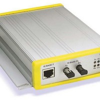
The following table explains the function of the four network LEDs.
1-8
nterface cable for the RS 32 Serial interface. The UDS-M-SBC is an optional male
DTR
DSR
LED
GL (Good Link)
Tx (Network Transmit)
Rx (Network Receive)
Co (Collision)
he serial device can be
.8 Serial In
.9 Netw
DTE,
CTS
RTS
Rx Co
Tx GL
9
8
7
6
9-Pin, FEMALE
5
ork LED
4
3
2
1
AC/DC
9-30V
GND
TXD
RXD
block con
terface
RS
s
-2
nector.
RX(in)
-232 or RS-485/422. The following diagram shows a typica
Meaning
Lights solid green to indicate network po
the network.
Blinks yellow to indicate network pa
Blinks yellow to indicate netwo
Blinks red to indicate network collisions.
ected to a seria
TX(in)
Cable
DCE, 25-Pin, MALE
5
4
3
2
13
1
25
14
20
6
l or Ethernet device for setup and configuration.
rk packets are receiving.
ckets are transmitting.
rt is connected to
CoBox-FL User Guide
DB-25
l
Related parts for COBOX-FL-11
Image
Part Number
Description
Manufacturer
Datasheet
Request
R

Part Number:
Description:
Ethernet Modules & Development Tools COBOX FL IAP-11 Industrial
Manufacturer:
Lantronix
Datasheet:
Part Number:
Description:
Ethernet Modules & Development Tools 2-Port
Manufacturer:
Lantronix
Datasheet:


Part Number:
Description:
Ethernet Modules & Development Tools XPort Pro Sample Ext Temp Encryp&Evol OS
Manufacturer:
Lantronix
Datasheet:
Part Number:
Description:
Ethernet Modules & Development Tools XPort Pro Sample Ext Temp Encryp&Linux OS
Manufacturer:
Lantronix
Datasheet:

Part Number:
Description:
WiFi / 802.11 Modules & Development Tools MatchPort Demo Kit Module not included
Manufacturer:
Lantronix
Datasheet:

Part Number:
Description:
Development Software MatchPort Developer Kit
Manufacturer:
Lantronix

Part Number:
Description:
Ethernet & Other Communication Accessories XPress-Pro SW 92000 8-Port 10/100TX
Manufacturer:
Lantronix
Datasheet:

Part Number:
Description:
Ethernet & Other Communication Accessories XPress-Pro SW 52000 Ind 5-Port 10/100TX
Manufacturer:
Lantronix
Datasheet:
Part Number:
Description:
Ethernet Modules & Development Tools XPort Pro Ext. Temp w/ Encryp & Evol OS
Manufacturer:
Lantronix
Datasheet:

Part Number:
Description:
Sun Microsystems, TTL, 8 pin mini-din and DB9 serial port
Manufacturer:
Lantronix
Datasheet:
Part Number:
Description:
Transceiver, DVI-Fiberlynx, PS/2KB/Mouse, Transmitter
Manufacturer:
Lantronix
Part Number:
Description:
Ethernet, SecureBox SDS1100 Single-Port Secure Device Server
Manufacturer:
Lantronix
Part Number:
Description:
Communications, The MPS/LPS Micro Print Servers
Manufacturer:
Lantronix
Datasheet:
Part Number:
Description:
WiFi / 802.11 Modules PremierWaveXN 802.11 Device Server US
Manufacturer:
Lantronix
Datasheet: