C8051F206DK-G Silicon Laboratories Inc, C8051F206DK-G Datasheet - Page 7
C8051F206DK-G
Manufacturer Part Number
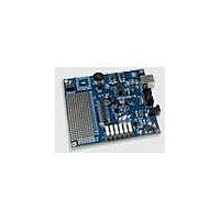
C8051F206DK-G
Description
MCU, MPU & DSP Development Tools MCU DEVELOPMENT KIT W/ GLOBAL POWER SPLY
Manufacturer
Silicon Laboratories Inc
Datasheet
1.C8051F226DK.pdf
(146 pages)
Specifications of C8051F206DK-G
Processor To Be Evaluated
C8051F206
Data Bus Width
8 bit
Interface Type
USB
Lead Free Status / RoHS Status
Lead free / RoHS Compliant


List of Figures and Tables
1. System Overview
2. Absolute Maximum Ratings
3. Global DC Electrical Characteristics
4. Pinout and Package Definitions
5. ADC (8-Bit, C8051F220/1/6 Only)
6. ADC (12-Bit, C8051F206 Only)
7. Voltage Reference (C8051F206/220/221/226)
8. Comparators
9. CIP-51 Microcontroller
Table 1.1. Product Selection Guide ........................................................................ 11
Figure 1.1. C8051F206, C8051F220 and C8051F226 Block Diagram (48 TQFP) .. 12
Figure 1.2. C8051F221 Block Diagram (32 LQFP) .................................................. 13
Figure 1.3. C8051F230 and C8051F236 Block Diagram (48 TQFP) ....................... 14
Figure 1.4. C8051F231 Block Diagram (32 LQFP) .................................................. 15
Figure 1.5. Comparison of Peak MCU Throughputs ................................................ 16
Figure 1.6. Comparison of Peak MCU Throughputs ................................................ 17
Figure 1.7. On-Board Memory Map.......................................................................... 18
Figure 1.8. Degub Environment Diagram................................................................. 19
Figure 1.9. Port I/O Functional Block Diagram......................................................... 20
Figure 1.10. ADC Diagram ....................................................................................... 21
Figure 1.11. Comparator Diagram............................................................................ 22
Table 2.1. Absolute Maximum Ratings* .................................................................. 23
Table 3.1. Global DC Electrical Characteristics ...................................................... 24
Table 4.1. Pin Definitions ........................................................................................ 25
Figure 4.1. TQFP-48 Pin Diagram............................................................................ 28
Figure 4.2. LQFP-32 Pin Diagram............................................................................ 29
Figure 4.3. TQFP-48 Package Drawing ................................................................... 30
Figure 4.4. LQFP-32 Package Drawing ................................................................... 31
Figure 5.1. 8-Bit ADC Functional Block Diagram ..................................................... 32
Figure 5.2. 12-Bit ADC Track and Conversion Example Timing .............................. 33
Figure 5.3. 8-Bit ADC Window Interrupt Examples .................................................. 38
Table 5.1. 8-Bit ADC Electrical Characteristics....................................................... 39
Figure 6.1. 12-Bit ADC Functional Block Diagram ................................................... 40
Figure 6.2. 12-Bit ADC Track and Conversion Example Timing .............................. 41
Figure 6.3. 12-Bit ADC Window Interrupt Examples, Right Justified Data ............... 47
Figure 6.4. 12-Bit ADC Window Interrupt Examples, Left Justified Data ................. 48
Table 6.1. 12-Bit ADC Electrical Characteristics (C8015F206 only) ....................... 49
Figure 7.1. Voltage Reference Functional Block Diagram ....................................... 50
Table 7.1. Reference Electrical Characteristics ...................................................... 51
Figure 8.1. Comparator Functional Block Diagram .................................................. 53
Figure 8.2. Comparator Hysteresis Plot ................................................................... 54
Table 8.1. Comparator Electrical Characteristics.................................................... 57
Figure 9.1. CIP-51 Block Diagram............................................................................ 58
Rev. 1.6
C8051F2xx
7
Related parts for C8051F206DK-G
Image
Part Number
Description
Manufacturer
Datasheet
Request
R

Part Number:
Description:
SMD/C°/SINGLE-ENDED OUTPUT SILICON OSCILLATOR
Manufacturer:
Silicon Laboratories Inc
Part Number:
Description:
Manufacturer:
Silicon Laboratories Inc
Datasheet:
Part Number:
Description:
N/A N/A/SI4010 AES KEYFOB DEMO WITH LCD RX
Manufacturer:
Silicon Laboratories Inc
Datasheet:
Part Number:
Description:
N/A N/A/SI4010 SIMPLIFIED KEY FOB DEMO WITH LED RX
Manufacturer:
Silicon Laboratories Inc
Datasheet:
Part Number:
Description:
N/A/-40 TO 85 OC/EZLINK MODULE; F930/4432 HIGH BAND (REV E/B1)
Manufacturer:
Silicon Laboratories Inc
Part Number:
Description:
EZLink Module; F930/4432 Low Band (rev e/B1)
Manufacturer:
Silicon Laboratories Inc
Part Number:
Description:
I°/4460 10 DBM RADIO TEST CARD 434 MHZ
Manufacturer:
Silicon Laboratories Inc
Part Number:
Description:
I°/4461 14 DBM RADIO TEST CARD 868 MHZ
Manufacturer:
Silicon Laboratories Inc
Part Number:
Description:
I°/4463 20 DBM RFSWITCH RADIO TEST CARD 460 MHZ
Manufacturer:
Silicon Laboratories Inc
Part Number:
Description:
I°/4463 20 DBM RADIO TEST CARD 868 MHZ
Manufacturer:
Silicon Laboratories Inc
Part Number:
Description:
I°/4463 27 DBM RADIO TEST CARD 868 MHZ
Manufacturer:
Silicon Laboratories Inc
Part Number:
Description:
I°/4463 SKYWORKS 30 DBM RADIO TEST CARD 915 MHZ
Manufacturer:
Silicon Laboratories Inc
Part Number:
Description:
N/A N/A/-40 TO 85 OC/4463 RFMD 30 DBM RADIO TEST CARD 915 MHZ
Manufacturer:
Silicon Laboratories Inc
Part Number:
Description:
I°/4463 20 DBM RADIO TEST CARD 169 MHZ
Manufacturer:
Silicon Laboratories Inc