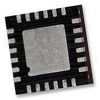
ITG-3200 INVENSENSE, ITG-3200 Datasheet - Page 26

ITG-3200
Manufacturer Part Number
ITG-3200
Description
IC, GYRO, TRI-AXIS, +/-2000 DEG/S
Manufacturer
INVENSENSE
Datasheet
1.ITG-3200.pdf
(39 pages)
Specifications of ITG-3200
No. Of Axes
3
Sensor Case Style
QFN
No. Of Pins
24
Supply Voltage Range
2.1V To 3.6V
Operating Temperature Range
-40°C To +85°C
Interface
I2C, Serial
Interface Type
I2C, Serial
Rohs Compliant
Yes
Lead Free Status / RoHS Status
Lead free / RoHS Compliant
Available stocks
Company
Part Number
Manufacturer
Quantity
Price
Part Number:
ITG-3200
Manufacturer:
INVENSE
Quantity:
20 000
8.4
8.5
Register 23 – Interrupt Configuration
Register 26 – Interrupt Status
Type: Read/Write
Description:
This register configures the interrupt operation of the device. The interrupt output pin (INT) configuration can
be set, the interrupt latching/clearing method can be set, and the triggers for the interrupt can be set.
Note that if the application requires reading every sample of data from the ITG-3200 part, it is best to enable
the raw data ready interrupt (RAW_RDY_EN). This allows the application to know when new sample data is
available.
Parameters:
ACTL
OPEN
LATCH_INT_EN
INT_ANYRD_2CLEAR
ITG_RDY_EN
RAW_RDY_EN
0
Type: Read only
Description:
This register is used to determine the status of the ITG-3200 interrupts. Whenever one of the interrupt sources
is triggered, the corresponding bit will be set. The polarity of the interrupt pin (active high/low) and the latch
type (pulse or latch) has no affect on these status bits.
Use the Interrupt Configuration register (23) to enable the interrupt triggers. If the interrupt is not enabled, the
associated status bit will not get set.
In normal use, the RAW_DATA_RDY interrupt is used to determine when new sensor data is available in either
the sensor registers (27 to 32).
Interrupt Status bits get cleared as determined by INT_ANYRD_2CLEAR in the interrupt configuration
register (23).
Parameters:
ITG_RDY
RAW_DATA_RDY
Register
Register
(Hex)
(Hex)
1A
17
(Decimal)
(Decimal)
Register
Register
23
26
PLL ready
Raw data is ready
ACTL
Bit7
Logic level for INT output pin – 1=active low, 0=active high
Drive type for INT output pin – 1=open drain, 0=push-pull
Latch mode – 1=latch until interrupt is cleared, 0=50us pulse
Latch clear method – 1=any register read, 0=status register read only
Enable interrupt when device is ready (PLL ready after changing clock source)
Enable interrupt when data is available
Load zeros into Bits 1 and 3 of the Interrupt Configuration register.
Bit7
ITG-3200 Product Specification
-
OPEN
Bit6
Bit6
-
LATCH_
INT_EN
Bit5
Bit5
-
ANYRD_
2CLEAR
INT_
Bit4
Bit4
-
Bit3
Bit3
0
-
ITG_RDY_
Document Number: PS-ITG-3200A-00-01.4
Revision: 1.4
Release Date: 03/30/2010
ITG_RDY
Bit2
EN
Bit2
Bit1
Bit1
0
-
26 of 39
RDY_ EN
RAW_
DATA_
Bit0
RAW_
RDY
Bit0
Default
Default
Value
Value
00h
00h


