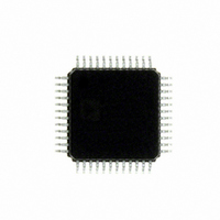
ADUC7060BSTZ32 Analog Devices Inc, ADUC7060BSTZ32 Datasheet - Page 3

ADUC7060BSTZ32
Manufacturer Part Number
ADUC7060BSTZ32
Description
DUAL 24-BIT AFE AND ARM 7 I.C
Manufacturer
Analog Devices Inc
Series
MicroConverter® ADuC7xxxr
Specifications of ADUC7060BSTZ32
Design Resources
4 mA-to-20 mA Loop-Powered Temperature Monitor Using ADuC7060/1 (CN0145) Low power, Long Range, ISM Wireless Measuring Node (CN0164)
Core Processor
ARM7
Core Size
16/32-Bit
Speed
10MHz
Connectivity
I²C, SPI, UART/USART
Peripherals
POR, PWM, Temp Sensor, WDT
Number Of I /o
14
Program Memory Size
32KB (16K x 16)
Program Memory Type
FLASH
Ram Size
4K x 8
Voltage - Supply (vcc/vdd)
2.375 V ~ 2.625 V
Data Converters
A/D 5x24b, 8x24b, D/A 1x14b
Oscillator Type
Internal
Operating Temperature
-40°C ~ 125°C
Package / Case
48-LQFP
Cpu Family
ADuC7xxx
Device Core
ARM7TDMI
Device Core Size
16/32Bit
Frequency (max)
10.24MHz
Interface Type
I2C/SPI/UART
Total Internal Ram Size
4KB
# I/os (max)
14
Number Of Timers - General Purpose
4
Operating Supply Voltage (typ)
2.5V
Operating Supply Voltage (max)
2.625V
Operating Supply Voltage (min)
2.375V
On-chip Adc
2(4-chx24-bit)
Instruction Set Architecture
RISC
Operating Temp Range
-40C to 125C
Operating Temperature Classification
Automotive
Mounting
Surface Mount
Pin Count
48
Package Type
LQFP
Package
48LQFP
Family Name
ADuC7xxx
Maximum Speed
10.24 MHz
Operating Supply Voltage
2.5 V
Data Bus Width
16|32 Bit
Number Of Programmable I/os
14
Number Of Timers
4
Lead Free Status / RoHS Status
Lead free / RoHS Compliant
Eeprom Size
-
Lead Free Status / Rohs Status
Compliant
Available stocks
Company
Part Number
Manufacturer
Quantity
Price
Company:
Part Number:
ADUC7060BSTZ32
Manufacturer:
CYPRESS
Quantity:
294
Company:
Part Number:
ADUC7060BSTZ32
Manufacturer:
ADI
Quantity:
315
Company:
Part Number:
ADUC7060BSTZ32
Manufacturer:
Analog Devices Inc
Quantity:
10 000
Part Number:
ADUC7060BSTZ32
Manufacturer:
ADI/亚德诺
Quantity:
20 000
Company:
Part Number:
ADUC7060BSTZ32-RL
Manufacturer:
Analog Devices Inc
Quantity:
10 000
Hardware Design Considerations .............................................. 104
REVISION HISTORY
5/11—Rev. B to Rev. C
Change to Figure 1 ............................................................................4
Changes to Table 1 ............................................................................6
Add Temporary Protection Section and Keyed Permanent
Protection Section ...........................................................................25
Added Permanent Protection Section and Sequence to Write
the Software Protection Key and Set Permanent Protection
Section ..............................................................................................26
Changes to Power Control System Section..................................35
Changes to Bit 9:6, Table 43 ...........................................................45
Changes to Primary Channel ADC Data Register Section and
Table 49.............................................................................................50
Changes to IRQEN Section and IRQCLR Section .....................59
Changes to Timer1 or Wake-Up Timer Section .........................69
Changes to Table 108 ....................................................................101
2/10—Rev. A to Rev. B
Changes to Features Section ............................................................1
Changes to Table 1 ............................................................................4
Changes to Digital I/O Voltage to DGND Parameter ................14
Changes to Pin 19, Pin 20, and Pin 45 Descriptions (Table 8)..16
Changes to Pin 13, Pin 14, and Pin 29 Descriptions (Table 9)..18
Changes to Bit 8 in Table 14...........................................................23
Changes to Table 20 ........................................................................28
Changes to Power Control System Section..................................34
Added Table 32 ................................................................................35
Changes to Endnote 2 and Endnote 3 of Table 34 ......................36
Changes to Table 42 ........................................................................42
Changes to Bit 12 and Bits[3:0] in Table 43 .................................44
Changes to Bit 12 in Table 44 ........................................................45
Changes to Endnote 2 in Table 45.................................................47
Changes to Bit 5 in Table 63...........................................................55
Changes to Serial Downloading (In-Circuit Programming)
Section ..............................................................................................57
Changes to Priority Registers Section ..........................................61
Changes to GPxPAR Registers Section ......................................101
6/09—Rev. 0 to Rev. A
Added ADuC7061.............................................................. Universal
Added New Package CP-32-4........................................... Universal
Changes to Features Section ............................................................1
Changes to General Description Section .......................................1
Changes to Figure 1...........................................................................4
Power Supplies.......................................................................... 104
Rev. C | Page 3 of 108
Outline Dimensions......................................................................105
Changes to Table 1 ............................................................................7
Deleted Endnote to Table 2............................................................10
Changes to Endnotes, Table 3 and Table 4...................................11
Changes to Endnotes, Table 5........................................................12
Changes to Endnotes, Table 6........................................................13
Changes to Figure 7 and Table 8 ...................................................15
Added Figure 8 and Table 9, Renumbered Sequentially............18
Changes to Flash EE/Control Interface Section..........................23
Change to Code 0x04 Description, Table 15 ...............................24
Change to Bit 31 Description, Table 16........................................25
Changes to Table 17 ........................................................................27
Changes to Table 19 T0CLRI and Table 20..................................28
Changes to Endnote, Table 21 .......................................................29
Change to SPITX Default Value, Table 25 ...................................30
Changes to External Clock Selection Section .............................33
Changes to ADC Circuit Information Section............................36
Change to Column Heading Table 35 ..........................................37
Change to Bit 6 Description, Table 39..........................................40
Change to Bit 12 Description, Table 43........................................44
Changes to Primary Channel ADC Data Register Section
and Auxiliary Channel ADC Data Register Section ..................48
Change to Table 59 and Figure 17.................................................51
Changes to Using the DAC Section ..............................................55
Changes to Nonvolatile Flash/EE Memory Section and
Programming Section.....................................................................56
Changes to Vectored Interrupt Controller (VIC) Section.........59
Changes to Priority Registers Section ..........................................60
Change to Table 73..........................................................................61
Changes to Figure 23 ......................................................................65
Changes Table 78.............................................................................66
Changes to Figure 24 and Table 79 ...............................................68
Changes to Timer2 Interface Section and Figure 25 ..................69
Changes to Timer3 Capture Register Section .............................71
Change to Bits[16:12] Description, Table 81...............................72
Changes Pulse-Width Modulator General Overview Section,
Table 82, and Figure 26...................................................................73
Changes to Table 84 Column Headings .......................................75
Changes to Table 92 ........................................................................82
Changes to Bit 1, Table 102............................................................90
Changes to Bit 11 Description, Table 105 ....................................95
Changes to SPIMDE Bit Description, Table 106.........................97
Updated Outline Dimensions......................................................103
Changes to Ordering Guide.........................................................104
4/09—Revision 0: Initial Version
Ordering Guide .........................................................................106
ADuC7060/ADuC7061


