EVAL-ADF7021-NDBEZ Analog Devices Inc, EVAL-ADF7021-NDBEZ Datasheet - Page 36
EVAL-ADF7021-NDBEZ
Manufacturer Part Number
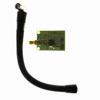
EVAL-ADF7021-NDBEZ
Description
426MHz To 429 MHz, External L
Manufacturer
Analog Devices Inc
Type
Transceiver, FSKr
Datasheet
1.ADF7021-NBCPZ-RL.pdf
(64 pages)
Specifications of EVAL-ADF7021-NDBEZ
Frequency
420MHz ~ 440MHz
Lead Free Status / RoHS Status
Lead free / RoHS Compliant
For Use With/related Products
ADF7021-N
Lead Free Status / RoHS Status
Lead free / RoHS Compliant
Other names
Q5835434A


ADF7021-N
DEMODULATOR CONSIDERATIONS
2FSK Preamble
The recommended preamble bit pattern for 2FSK is a dc-free
pattern (such as a 10101010… pattern). Preamble patterns with
longer run-length constraints (such as 11001100…) can also be
used but result in a longer synchronization time of the received
bit stream in the receiver. The preamble needs to allow enough
bits for AGC settling of the receiver and CDR acquisition. A
minimum of 16 preamble bits is recommended when using the
correlator demodulator and 48 bits when using the linear demod-
ulator. When the receiver uses the internal AFC, the minimum
recommended number of preamble bits is 64.
The remaining fields that follow the preamble header do not
have to use dc-free coding. For these fields, the ADF7021-N can
accommodate coding schemes with a run length of greater than
eight bits without any performance degradation. Refer to
Application Note AN-915 for more information.
4FSK Preamble and Data Coding
The recommended preamble bit pattern for 4FSK is a repeating
00100010… bit sequence. This 2-level sequence of repeating
−3, +3, −3, +3 symbols is dc-free and maximizes the symbol
timing performance and data recovery of the 4FSK preamble in
the receiver. The minimum recommended length of the
preamble is 32 bits (16 symbols).
The remainder of the 4FSK packet should be constructed so
that the transmitted symbols retain close to a dc-free balance by
using data scrambling and/or by inserting specific dc balancing
symbols in the transmitted bit stream at regular intervals, such
as after every 8 or 16 symbols.
Demodulator Tolerance to Frequency Errors
Without AFC
The ADF7021-N has a number of options to combat frequency
errors that exist due to mismatches between the transmit and
receive crystals/TCXOs.
With AFC disabled, the correlator demodulator is tolerant to
frequency errors over a ±0.3 × f
frequency deviation. For larger frequency errors, the frequency
tolerance can be increased by adjusting the value of K and thus
doubling the correlator bandwidth.
K should then be calculated as
The DISCRIMINATOR_BW setting in Register 4 should also be
recalculated using the new K value. Doubling the correlator
bandwidth to improve frequency error tolerance in this manner
typically results in a 1 dB to 2 dB loss in receiver sensitivity.
K
=
Round
⎛
⎜
⎜
⎝
100
2
×
×
f
DEV
10
3
⎞
⎟
⎟
⎠
DEV
range, where f
DEV
is the FSK
Rev. 0 | Page 36 of 64
The linear demodulator (AFC disabled) tracks frequency errors
in the receive signal when the receive signal is within the IF
filter bandwidth. For example, for a receive signal with an
occupied bandwith = 9 kHz, using the 18.5 kHz IF filter
bandwidth allows the linear demodulator to track the signal at
an error of ±4.75 kHz with no increase in bit errors or loss in
sensitivity.
Correlator Demodulator and Low Modulation Indices
The modulation index in 2FSK is defined as
The receiver sensitivity performance and receiver frequency
tolerance can be maximized at low modulation index by
increasing the discriminator bandwidth of the correlator
demodulator. For modulation indices of less than 0.4, it is
recommended to double the correlator bandwidth by
calculating K as follows:
The DISCRIMINATOR_BW in Register 4 should be recalculated
using the new K value. Figure 27 highlights the improved
sensitivity that can be achieved for 2FSK modulation, at low
modulation indices, by doubling the correlator bandwidth.
AFC OPERATION
The ADF7021-N also supports a real-time AFC loop that is
used to remove frequency errors due to mismatches between
the transmit and receive crystals/TCXOs. The AFC loop uses
the linear frequency discriminator block to estimate frequency
errors. The linear FSK discriminator output is filtered and
averaged to remove the FSK frequency modulation using a
combined averaging filter and envelope detector. In receive
mode, the output of the envelope detector provides an estimate
of the average IF frequency.
Two methods of AFC supported on the ADF7021-N are
external AFC and internal AFC.
External AFC
Here, the user reads back the frequency information through
the ADF7021-N serial port and applies a frequency correction
value to the fractional-N synthesizer-N divider.
The frequency information is obtained by reading the 16-bit
signed AFC readback, as described in the Readback Format
section, and by applying the following formula:
Although the AFC READBACK value is a signed number, under
normal operating conditions, it is positive. In the absence of
frequency errors, the frequency readback value is equal to the
IF frequency of 100 kHz.
Frequency Readback [Hz] = (AFC READBACK × DEMOD
K
Modulation
CLK)/2
=
Round
18
⎛
⎜ ⎜
⎝
Index
2
100
×
f
DEV
=
3
Data
2
⎞
⎟ ⎟
⎠
×
f
DEV
Rate
Related parts for EVAL-ADF7021-NDBEZ
Image
Part Number
Description
Manufacturer
Datasheet
Request
R

Part Number:
Description:
±1.7g Dual-Axis IMEMS Accelerometer Evaluation Board
Manufacturer:
Analog Devices Inc
Datasheet:

Part Number:
Description:
Inertial Sensor Evaluation System
Manufacturer:
Analog Devices Inc
Datasheet:
Part Number:
Description:
Manufacturer:
Analog Devices Inc
Datasheet:
Part Number:
Description:
Manufacturer:
Analog Devices Inc
Datasheet:
Part Number:
Description:
Manufacturer:
Analog Devices Inc
Datasheet:
Part Number:
Description:
Manufacturer:
Analog Devices Inc
Datasheet:
Part Number:
Description:
Manufacturer:
Analog Devices Inc
Datasheet:
Part Number:
Description:
Manufacturer:
Analog Devices Inc
Datasheet:
Part Number:
Description:
Manufacturer:
Analog Devices Inc
Datasheet:
Part Number:
Description:
Manufacturer:
Analog Devices Inc
Datasheet:
Part Number:
Description:
Manufacturer:
Analog Devices Inc
Datasheet:
Part Number:
Description:
Manufacturer:
Analog Devices Inc
Datasheet:
Part Number:
Description:
Manufacturer:
Analog Devices Inc
Datasheet: