EVAL-ADF7021-NDBEZ Analog Devices Inc, EVAL-ADF7021-NDBEZ Datasheet - Page 37
EVAL-ADF7021-NDBEZ
Manufacturer Part Number
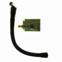
EVAL-ADF7021-NDBEZ
Description
426MHz To 429 MHz, External L
Manufacturer
Analog Devices Inc
Type
Transceiver, FSKr
Datasheet
1.ADF7021-NBCPZ-RL.pdf
(64 pages)
Specifications of EVAL-ADF7021-NDBEZ
Frequency
420MHz ~ 440MHz
Lead Free Status / RoHS Status
Lead free / RoHS Compliant
For Use With/related Products
ADF7021-N
Lead Free Status / RoHS Status
Lead free / RoHS Compliant
Other names
Q5835434A


Internal AFC
The ADF7021-N supports a real-time, internal, automatic
frequency control loop. In this mode, an internal control loop
automatically monitors the frequency error and adjusts the
synthesizer-N divider using an internal proportional integral
(PI) control loop.
The internal AFC control loop parameters are controlled in
Register 10. The internal AFC loop is activated by setting
R10_DB4 to 1. A scaling coefficient must also be entered, based
on the crystal frequency in use. This is set up in R10_DB[5:16]
and should be calculated using
Maximum AFC Range
The maximum frequency correction range of the AFC loop is
programmable on the ADF7021-N. This is set by R10_DB[24:31].
The maximum AFC correction range is the difference in
frequency between the upper and lower limits of the AFC
tuning range. For example, if the maximum AFC correction
range is set to 10 kHz, the AFC can adjust the receiver LO
within the f
However, when RF_DIVIDE_BY_2 (R1_DB18) is enabled, the
programmed range is halved. The user should account for this
halving by doubling the programmed maximum AFC range.
The recommended maximum AFC correction range should be
≤1.5 × IF filter bandwidth. If the maximum frequency correction
range is set to be >1.5 × IF filter bandwidth, the attenuation of
the IF filter can degrade the AFC loop sensitivity.
The adjacent channel rejection (ACR) performance of the
receivers can be degraded when AFC is enabled and the AFC
correction range is close to the IF filter bandwidth. However,
because the AFC correction range is programmable, the user
can trade off correction range and ACR performance.
AFC
_
LO
SCALING
± 5 kHz range.
_
FACTOR
=
Round
⎛
⎜
⎜
⎝
2
24
XTAL
×
500
⎞
⎟
⎟
⎠
Rev. 0 | Page 37 of 64
When AFC errors are removed using either the internal or
external AFC, further improvement in receiver sensitivity can
be obtained by reducing the IF filter bandwidth using the
IF_FILTER_BW bits (R4_DB[30:31]).
AUTOMATIC SYNC WORD DETECTION (SWD)
The ADF7021-N also supports automatic detection of the sync
or ID fields. To activate this mode, the sync (or ID) word must
be preprogrammed into the ADF7021-N. In receive mode, this
preprogrammed word is compared to the received bit stream.
When a valid match is identified, the external SWD pin is
asserted by the ADF7021-N on the next Rx clock pulse.
This feature can be used to alert the microprocessor that a
valid channel has been detected. It relaxes the computational
requirements of the microprocessor and reduces the overall
power consumption.
The SWD signal can also be used to frame the received packet
by staying high for a preprogrammed number of bytes. The data
packet length can be set in R12_DB[8:15].
The SWD pin status can be configured by setting R12_DB[6:7].
R11_DB[4:5] are used to set the length of the sync/ID word, which
can be 12, 16, 20, or 24 bits long. A value of 24 bits is recommended
to minimize false sync word detection in the receiver that can
occur during recovery of the remainder of the packet or when a
noise/no signal is present at the receiver input. The transmitter
must transmit the sync byte MSB first and the LSB last to ensure
proper alignment in the receiver sync-byte-detection hardware.
An error tolerance parameter can also be programmed that
accepts a valid match when up to three bits of the word are
incorrect. The error tolerance value is assigned in R11_DB[6:7].
ADF7021-N
Related parts for EVAL-ADF7021-NDBEZ
Image
Part Number
Description
Manufacturer
Datasheet
Request
R

Part Number:
Description:
±1.7g Dual-Axis IMEMS Accelerometer Evaluation Board
Manufacturer:
Analog Devices Inc
Datasheet:

Part Number:
Description:
Inertial Sensor Evaluation System
Manufacturer:
Analog Devices Inc
Datasheet:
Part Number:
Description:
Manufacturer:
Analog Devices Inc
Datasheet:
Part Number:
Description:
Manufacturer:
Analog Devices Inc
Datasheet:
Part Number:
Description:
Manufacturer:
Analog Devices Inc
Datasheet:
Part Number:
Description:
Manufacturer:
Analog Devices Inc
Datasheet:
Part Number:
Description:
Manufacturer:
Analog Devices Inc
Datasheet:
Part Number:
Description:
Manufacturer:
Analog Devices Inc
Datasheet:
Part Number:
Description:
Manufacturer:
Analog Devices Inc
Datasheet:
Part Number:
Description:
Manufacturer:
Analog Devices Inc
Datasheet:
Part Number:
Description:
Manufacturer:
Analog Devices Inc
Datasheet:
Part Number:
Description:
Manufacturer:
Analog Devices Inc
Datasheet:
Part Number:
Description:
Manufacturer:
Analog Devices Inc
Datasheet: