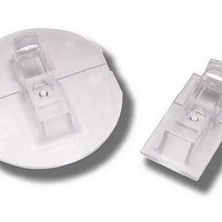
ADNS-2220 Avago Technologies US Inc., ADNS-2220 Datasheet - Page 21

ADNS-2220
Manufacturer Part Number
ADNS-2220
Description
SOLID STATE OPTICAL MOUSE LENS
Manufacturer
Avago Technologies US Inc.
Specifications of ADNS-2220
Lead Free Status / Rohs Status
Lead free / RoHS Compliant
Other names
Q2072083A
Notes on Power-up and the serial port Reset Circuit
The ADNS-3060 does not perform an internal power up
self-reset. The reset pin must be raised and lowered to
reset the chip. This should be done every time power is
applied. During power-up there will be a period of time
after the power supply is high but before any clocks are
available. The table below shows the state of the various
pins during power-up and reset when the RESET pin is
driven high by a micro-controller.
Power Down Circuit
The following table lists the pin states during power
down.
The chip is put into the power down (PD) mode by low-
ering the NPD input. When in PD mode, the oscillator is
21
State of Signal Pins After VDD is Valid
Pin
SPI pullups
NCS
MISO
SCLK
MOSI
LED_CTRL
RESET
NPD
State of Signal Pins During Power Down
Pin
SPI pullups
NCS
MISO
SCLK
MOSI
LED_CTRL
RESET
NPD
REFC
OSC_IN
OSC_OUT
Before Reset
Undefined
Hi-Z control
functional
Driven or hi-Z
(per NCS)
Undefined
Undefined
Undefined
Functional
Undefined
NPD low
off
hi-Z control functional
low or hi-Z (per NCS)
ignored
ignored
low
functional
low (driven externally)
V
low
high
DD3
During Reset
Off
Hi-Z control
functional
Driven or hi-Z
(per NCS)
Ignored
Ignored
Low
High
(externally driven)
Ignored
After wake from PD
pre-PD state
functional
pre-PD state or hi-Z
functional
functional
high
functional
functional
REFC
OSC_IN
OSC_OUT
After Reset
On (default)
Functional
Low or hi-Z
(per NCS)
Functional
Functional
High
Functional
Functional
stopped but all register contents are retained. To achieve
the lowest current state, all inputs must be held exter-
nally within 200mV of a rail, either ground or V
chip outputs are driven low or hi-Z during PD to prevent
current consumption by an external load.
LED Drive Mode
The LED has 2 modes of operation: DC and Shutter. In
DC mode it is on at all times the chip is powered except
when in the power down mode via the NPD pin. In shut-
ter mode the LED is on only during the portion of the
frame that light is required. The LED_MODE bit in the
Configuration_bits register sets the LED mode.
DD3
. The


