8845A/SU 120V Fluke Electronics, 8845A/SU 120V Datasheet - Page 40
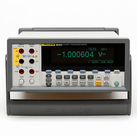
8845A/SU 120V
Manufacturer Part Number
8845A/SU 120V
Description
PREC MLTMTR DMM BNCH 6.5 DIG RES
Manufacturer
Fluke Electronics
Type
Digital (DMM)r
Specifications of 8845A/SU 120V
Includes
Test Leads
Style
Bench
Display Digits
6.5
Display Type
VFD, Dual
Display Count
Varies
Function
Voltage, Current, Resistance, Frequency
Functions, Extra
Continuity, dB, Diode Test
Features
Memory, RS-232
Ranging
Manual
Response
Average
Lead Free Status / RoHS Status
Contains lead / RoHS compliant by exemption
Other names
2675292
614-1001
614-1001


8845A/8846A
Users Manual
2-8
Turning Power-On
Adjusting the Bail
Installing the Meter in an Equipment Rack
1
3
With the proper line voltage selected and the appropriate power cord connected to the
Meter, connect the power cord to a power outlet and switch rear-panel power switch so
the “I” side of the switch is depressed.
For bench-top use, the Meter’s bail or handle is adjustable to provide two viewing angles.
To adjust its position, pull the ends out to a hard stop (about 1/4-inch on each side) and
rotate it to one of the four stop positions shown in Figure 2-4. To completely remove the
handle, adjust it to the vertical stop position and pull the ends all the way out.
The Meter is mountable in a standard 19-inch rack using a rack mount kit. See the
“Options and Accessories” section in Chapter 1 for ordering information. In preparation
for rack mounting, remove the bail (see the “Adjusting the Bail” section above) and the
front and rear protective boots. Then refer to the instructions provided with the Rack
Mount Kit to mount the Meter.
Store
Carry
To avoid electric shock, connect the Meter’s power cord to a
power receptacle with proper earth ground. A protective ground
connection by way of the grounding conductor in the power
cord is essential for safe operation.
Figure 2-4. Bail Adjustment and Removal
XW Warning
2
Tilt up
4
Remove
RANGE
BACK
F1
DC V
PERIOD
FREQ
ACV
F2
DC I
F3
TEMP
AC I
ZERO
F4
ANALYZE
TRIG
SETUP
SETUP
INSTR
MEAS
F5
MEMORY
caw017.eps