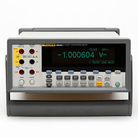
8845A/SU 120V Fluke Electronics, 8845A/SU 120V Datasheet - Page 86

8845A/SU 120V
Manufacturer Part Number
8845A/SU 120V
Description
PREC MLTMTR DMM BNCH 6.5 DIG RES
Manufacturer
Fluke Electronics
Type
Digital (DMM)r
Specifications of 8845A/SU 120V
Includes
Test Leads
Style
Bench
Display Digits
6.5
Display Type
VFD, Dual
Display Count
Varies
Function
Voltage, Current, Resistance, Frequency
Functions, Extra
Continuity, dB, Diode Test
Features
Memory, RS-232
Ranging
Manual
Response
Average
Lead Free Status / RoHS Status
Contains lead / RoHS compliant by exemption
Other names
2675292
614-1001
614-1001
8845A/8846A
Users Manual
4-18
Connecting an External Trigger
Monitoring the Measurement-Complete Signal
1. Press Lto display the measurement setup menu.
2. Press the TRIGGER soft key.
3. Press the soft key labeled #SAMPLES.
4. Use the soft keys to set the number of samples between 1 and 50,000.
5. Press ENTER.
The TRIG I/O jack on the Meter’s rear panel is used to connect to an external trigger
signal. The falling edge of a TTL signal will trigger the Meter to start taking
measurements, if the Meter is in external trigger mode.
Figure 4-9 indicates the purpose of the three pins in the TRIG I/O connector.
In addition to being a trigger input, the TRIG I/O jack on the Meter’s rear panel also
provides a signal indicating the completion of a measurement cycle. A falling edge of a
TTL signal indicates a measurement cycle is complete. See Figure 4-9 above to identify
which pins on the TRIG I/O connector are used to sense the measurement-complete
signal.
Select the digit in the value by pressing either <-- or -->.
With the digit selected, press the soft key labeled -- to decrement the digit or ++ to
increment the character.
Pin 1: Trigger In
Figure 4-9. TRIG I/O Pin-out Description
TRIG I/O
Pin 2: Signal Ground
Pin 3: Measure Complete Out
caw059.eps


