ZEN-10C2AR-A-V2 Omron, ZEN-10C2AR-A-V2 Datasheet - Page 59
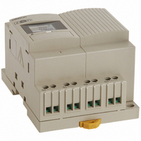
ZEN-10C2AR-A-V2
Manufacturer Part Number
ZEN-10C2AR-A-V2
Description
100/240 VAC 6 IN, 4 OUT
Manufacturer
Omron
Series
ZEN V2r
Type
Expandabler
Datasheets
1.ZEN-BAT01_OMS.pdf
(37 pages)
2.ZEN-SOFT01-V4.pdf
(35 pages)
3.ZEN-10C1DR-D-V2.pdf
(61 pages)
4.ZEN-10C1DR-D-V2.pdf
(194 pages)
Specifications of ZEN-10C2AR-A-V2
Voltage - Supply
100 ~ 240VAC
Number Of I /o
6 Input, 4 Output
Display Type
LED
Output Type
Relay
Voltage Rating
100 V to 240 V
Input Type
AC
Lead Free Status / RoHS Status
Lead free / RoHS Compliant
Kit Contents
-
Analog Inputs
-
Lead Free Status / Rohs Status
Lead free / RoHS Compliant
Other names
Z2680
ZEN10C2ARAV2
ZEN10C2ARAV2


Mounting
2-1
2-1-1
Protection by Cover
Protection by Location
Protection by Barrier
2-1-2
36
Electrical shock may occur. Do not remove the Expansion Unit connector
cover unless an Expansion Unit will be permanently installed.
1 Remove the Expansion Unit connector cover from the side
Remove the cover screw with a Phillips screwdriver, insert a flat-blade
screwdriver into the gap around the cover, and remove the cover.
of the CPU Unit.
Phillips screwdriver
Mounting
Attention: Meeting the EC Low Voltage Directive
Connecting Expansion Units
A
Bottom View
The ZEN is an open-structure device. The right side of the enclosure (i.e., the
vertical surface where the Expansion Unit connector cover is located) does
not provide the mechanical strength against impact of a 500-g, 50-mm-dia.
steel ball from a height of 1,300 mm, as required in IEC/EN 61131-2.
Therefore, the ZEN must always be mounted inside a control panel and the
installation method must assure protection from such impact by using one of
the following installation methods.
Up to 3 Expansion Units can be connected.
Cover plate
(e.g., control panel)
B
Flat-blade screwdriver
Barrier
Insert insulation between the barrier and the ZEN if the
barrier is made of metal or other conductive material.
If another device is used as the barrier, use a class I device.
The area that needs to be protected against
mechanical impact. Install the ZEN close to the wall
of the control panel or in another location that will
protect it from mechanical impact.
Cover Hole Dimensions
N = Number of Expansion I/O Units
CPU Unit with 10 I/O points 47
CPU Unit with 20 I/O points 47
CAUTION
2 Insert the guides on the Expansion Unit into the CPU Unit.
3 Press the Expansion Unit and the CPU Unit together until
you can hear the connectors mate completely.
CPU Unit
A (mm)
70 + N × 35 + 2
122.5 + N × 35 + 2
Section 2-1
B (mm)
Related parts for ZEN-10C2AR-A-V2
Image
Part Number
Description
Manufacturer
Datasheet
Request
R

Part Number:
Description:
Controller; Zen Starter Kit, DC Model, Version 2
Manufacturer:
Omron Automation
Datasheet:

Part Number:
Description:
Programmble Controller Relay
Manufacturer:
Omron
Datasheet:
Part Number:
Description:
G6S-2GLow Signal Relay
Manufacturer:
Omron Corporation
Datasheet:
Part Number:
Description:
Compact, Low-cost, SSR Switching 5 to 20 A
Manufacturer:
Omron Corporation
Datasheet:
Part Number:
Description:
Manufacturer:
Omron Corporation
Datasheet:
Part Number:
Description:
Manufacturer:
Omron Corporation
Datasheet:
Part Number:
Description:
Manufacturer:
Omron Corporation
Datasheet:
Part Number:
Description:
Manufacturer:
Omron Corporation
Datasheet:
Part Number:
Description:
Manufacturer:
Omron Corporation
Datasheet:
Part Number:
Description:
Manufacturer:
Omron Corporation
Datasheet: