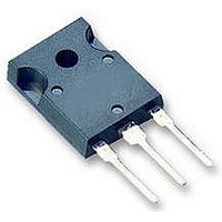
IKW08T120 Infineon Technologies, IKW08T120 Datasheet - Page 9

IKW08T120
Manufacturer Part Number
IKW08T120
Description
IGBT 1200V 16A 70W TO247-3
Manufacturer
Infineon Technologies
Series
TrenchStop™r
Datasheet
1.IKW08T120.pdf
(16 pages)
Specifications of IKW08T120
Igbt Type
NPT, Trench and Field Stop
Voltage - Collector Emitter Breakdown (max)
1200V
Vce(on) (max) @ Vge, Ic
2.2V @ 15V, 8A
Current - Collector (ic) (max)
16A
Power - Max
70W
Input Type
Standard
Mounting Type
Through Hole
Package / Case
TO-247-3 (Straight Leads)
Transistor Type
IGBT
Dc Collector Current
16A
Collector Emitter Voltage Vces
2.2V
Power Dissipation Max
70W
Collector Emitter Voltage V(br)ceo
1.2kV
Operating Temperature Range
-40°C To +150°C
Power Dissipation Pd
70W
Rohs Compliant
Yes
Switching Frequency
TRENCHSTOP 2-20kHz
Package
TO-247
Vce (max)
1,200.0 V
Ic(max) @ 25°
16.0 A
Ic(max) @ 100°
8.0 A
Lead Free Status / RoHS Status
Lead free / RoHS Compliant
Available stocks
Company
Part Number
Manufacturer
Quantity
Price
Company:
Part Number:
IKW08T120
Manufacturer:
NEC
Quantity:
30 000
Part Number:
IKW08T120
Manufacturer:
INFINEON/英飞凌
Quantity:
20 000
Part Number:
IKW08T120 K08T120
Manufacturer:
INFINEON/英飞凌
Quantity:
20 000
Power Semiconductors
6,0mJ
4,0mJ
2,0mJ
0,0mJ
Figure 13. Typical switching energy losses
2.0mJ
1.5mJ
1.0mJ
0.5mJ
0.0mJ
Figure 15. Typical switching energy losses
25°C
5A
*) E
*) E
due to diode recovery
T
due to diode recovery
as a function of collector current
(inductive load, T
V
Dynamic test circuit in Figure E)
as a function of junction
temperature
(inductive load, V
V
Dynamic test circuit in Figure E)
on
on
J
I
CE
GE
,
50°C
C
and E
and E
,
JUNCTION TEMPERATURE
=600V, V
=0/15V, I
COLLECTOR CURRENT
10A
ts
ts
include losses
include losses
75°C
C
GE
=8A, R
=0/15V, R
J
CE
=150°C,
100°C
=600V,
G
15A
=81Ω,
G
=81Ω,
125°C
TrenchStop
E
E
E
ts
on
E
off
E
*
9
E
*
on
ts
off
*
*
Figure 14. Typical switching energy losses
Figure 16. Typical switching energy losses
3,2 mJ
2,8 mJ
2,4 mJ
2,0 mJ
1,6 mJ
1,2 mJ
0,8 mJ
0,4 mJ
0,0 mJ
3mJ
2mJ
1mJ
0mJ
®
400V
Series
E
E
E
ts
V
off
on
*) E
*
*
CE
*) E
as a function of gate resistor
(inductive load, T
V
Dynamic test circuit in Figure E)
due to diode recovery
as a function of collector emitter
voltage
(inductive load, T
V
Dynamic test circuit in Figure E)
,
on
due to diode recovery
CE
COLLECTOR
GE
500V
and E
on
=600V, V
=0/15V, I
R
and E
G
,
ts
GATE RESISTOR
include losses
ts
600V
include losses
-
C
GE
EMITTER VOLTAGE
=8A, R
IKW08T120
=0/15V, I
J
J
=150°C,
=150°C,
700V
G
=81Ω,
Rev. 2.2 Dec 07
C
=8A,
800V
E
E
E
on
ts
off
*
*


