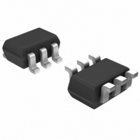
NMSD200B01-7 Diodes Inc, NMSD200B01-7 Datasheet - Page 2

NMSD200B01-7
Manufacturer Part Number
NMSD200B01-7
Description
MOSFET N-CH 60V 200MA SOT363
Manufacturer
Diodes Inc
Datasheet
1.NMSD200B01-7.pdf
(8 pages)
Specifications of NMSD200B01-7
Fet Type
MOSFET N-Channel, Metal Oxide
Fet Feature
Diode (Isolated)
Rds On (max) @ Id, Vgs
3 Ohm @ 50mA, 5V
Drain To Source Voltage (vdss)
60V
Current - Continuous Drain (id) @ 25° C
200mA
Vgs(th) (max) @ Id
3V @ 1mA
Input Capacitance (ciss) @ Vds
50pF @ 25V
Power - Max
200mW
Mounting Type
Surface Mount
Package / Case
SC-70-6, SC-88, SOT-363
Lead Free Status / RoHS Status
Lead free / RoHS Compliant
Gate Charge (qg) @ Vgs
-
Other names
NMSD200B01DITR
NMSD200B01TR
NMSD200B01TR
NMSD200B01TR
NMSD200B01TR
Electrical Characteristics: Schottky Barrier Diode (D1)
Maximum Ratings:
Sub-Component Device: ESD Protected N-Channel MOSFET (Q1)
Sub-Component Device: Schottky Diode (D1)
Electrical Characteristics:
ESD Protected N-Channel MOSFET (Q1)
Drain Source Voltage
Drain Gate Voltage (RGS <+ 1MOhm)
Gate Source Voltage
Drain Current (Page 1: Note 3)
Continuous Source Current
Peak Repetitive Reverse Voltage
Working Peak Reverse Voltage
DC Blocking Voltage
RMS Reverse Voltage
Forward Continuous Current (Page 1: Note 3)
Non-Repetitive Peak Forward Surge Current @ t<1.0 s
OFF CHARACTERISTICS (Note 4)
Drain-Source Breakdown Voltage, BV
Zero Gate Voltage Drain Current (Drain Leakage Current)
Gate Body Leakage Current, Forward
Gate Body Leakage Current, Reverse
ON CHARACTERISTICS (Note 4)
Gate Source Threshold Voltage (Control Supply Voltage)
Static Drain-Source On-State Voltage
On-State Drain Current
Static Drain-Source On Resistance
Forward Transconductance
Dynamic Characteristics
Input Capacitance
Output Capacitance
Reverse Transfer Capacitance
Switching Characteristics
Turn-On Delay Time
Turn-Off Delay Time
Drain-Source (Body) Diode Characteristics and Maximum Ratings
Drain-Source Diode Forward On-Voltage
Maximum Continuous Drain-Source Diode Forward Current
(Reverse Drain Current)
Maximum Pulsed Drain-Source Diode Forward Current
Reverse Breakdown Voltage (Note 4)
Forward Voltage Drop (Note 4)
Peak Reverse Current (Note 4)
Total Capacitance
Reverse Recovery Time
Notes:
DS30911 Rev. 7 - 2
4. Short duration pulse test used to minimize self-heating effect.
Characteristic
Characteristic
Characteristic
Characteristic
@T
A
= 25°C unless otherwise specified
DSS
Pulsed (tp<10uS, Duty Cycle<1%)
Symbol
V
V
(BR)R
I
C
RM
t
FM
rr
T
Continuous (V
Pulsed (tp<50 uS)
Min
40
⎯
⎯
⎯
⎯
⎯
Continuous
www.diodes.com
gs
V
Symbol
@T
R
V
V
BR(DSS)
I
=10V)
I
I
t
t
DS (on)
C
I
GSSF
GSSR
DS(on)
C
V
D(on)
C
GS(th)
g
d(on)
d(off)
I
DSS
I
SM
FS
oss
SD
iss
rss
S
A
= 25°C unless otherwise specified
Typ
2 of 8
28
10
⎯
⎯
⎯
⎯
@T
A
= 25°C unless otherwise specified
Min
500
1.1
60
80
⎯
⎯
⎯
⎯
⎯
⎯
⎯
⎯
⎯
⎯
⎯
⎯
⎯
⎯
⎯
1
Symbol
V
Symbol
V
V
0.37
Max
R(RMS)
V
I
0.6
V
V
I
FSM
⎯
⎯
⎯
RWM
RRM
VR
5
FM
DSS
DGR
GSS
I
I
D
S
0.09
0.62
1.25
0.88
Typ
260
1.6
1.8
1.6
@T
⎯
⎯
⎯
⎯
⎯
⎯
⎯
⎯
⎯
⎯
⎯
A
= 25°C unless otherwise specified
Max
1.25
300
800
-10
2.5
1.5
1.5
⎯
10
⎯
⎯
50
25
20
40
Unit
1
3
3
2
5
μA
pF
ns
V
V
Unit
mA
mS
mA
mA
μA
μA
μA
pF
pF
pF
I
I
I
V
V
I
Ω
ns
ns
V
V
V
V
V
V
R
F
F
F
R
R
=I
=20mA
=200mA
= 10μA
= 30V
= 0V, f = 1.0 MHz
R
= 200 mA, I
V
V
V
V
V
V
V
V
V
V
V
V
V
f = 1MHz
V
Value
Value
+/-20
+/-40
350
GS
GS
GS
GS
DS
DS
GS
GS
GS
GS
GS
DS
DS
GS
1.5
200
800
200
40
28
60
60
= V
Test Condition
= V
>=2*V
= 25V, V
= 0V, I
= 0V, I
= 20V, V
= -20 V, V
= 5V, I
= 10V, I
= 10V, V
= 5V, I
= 10V, I
= 0V, V
GS
GS
Test Condition
rr
=10V, I
= 0.1xI
= 10V, I
DS(ON),
D
D
D
S
= 50mA
D
D
DS
= 10μA
= 300 mA*
= 50mA
GS
DS
DS
= 500mA
= 500mA
DS
⎯
⎯
⎯
⎯
= 60V
© Diodes Incorporated
>=2*V
= 0V
= 0V,
R
D =
= 0V
I
NMSD200B01
, R
D =
D
=200mA
0.25mA
L
1mA
= 100 Ω
DS(ON)
Unit
Unit
mA
mA
mA
V
V
A
V
V
V


