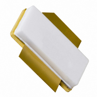
BLF573S,112 NXP Semiconductors, BLF573S,112 Datasheet - Page 4

BLF573S,112
Manufacturer Part Number
BLF573S,112
Description
TRANSISTOR RF LDMOS SOT502B
Manufacturer
NXP Semiconductors
Specifications of BLF573S,112
Transistor Type
LDMOS
Frequency
225MHz
Gain
27.2dB
Voltage - Rated
110V
Current Rating
42A
Current - Test
900mA
Voltage - Test
50V
Power - Output
300W
Package / Case
SOT502B
Application
HF/VHF
Channel Type
N
Channel Mode
Enhancement
Continuous Drain Current
42A
Drain Source Voltage (max)
110V
Output Power (max)
300W
Power Gain (typ)@vds
27.2@50VdB
Frequency (max)
225MHz
Package Type
LDMOST
Pin Count
3
Forward Transconductance (typ)
20S
Drain Source Resistance (max)
90(Typ)@6Vmohm
Input Capacitance (typ)@vds
300@50VpF
Output Capacitance (typ)@vds
103@50VpF
Reverse Capacitance (typ)
2.3@50VpF
Operating Temp Range
-65C to 225C
Drain Efficiency (typ)
70%
Mounting
Surface Mount
Mode Of Operation
CW
Number Of Elements
1
Vswr (max)
13
Screening Level
Military
Lead Free Status / RoHS Status
Lead free / RoHS Compliant
Noise Figure
-
Lead Free Status / Rohs Status
Compliant
Other names
934062175112
NXP Semiconductors
7. Application information
BLF573S_2
Product data sheet
6.1 Ruggedness in class-AB operation
7.1 Impedance information
The BLF573S is capable of withstanding a load mismatch corresponding to
VSWR = 13 : 1 through all phases under the following conditions: V
I
Table 8.
Measured Z
f
MHz
225
Dq
Fig 1.
Fig 2.
= 900 mA; P
V
Output capacitance as a function of drain-source voltage; capacitance value
without internal matching
Definition of transistor impedance
GS
Typical impedance
S
and Z
= 0 V; f = 1 MHz.
L
= 300 W; f = 225 MHz.
L
test circuit impedances.
C
Rev. 02 — 17 February 2009
(pF)
oss
800
600
400
200
0
0
Z
0.7 + j2.0
S
10
gate
Z
S
20
001aaf059
30
Z
drain
L
HF / VHF power LDMOS transistor
40
001aaj141
V
DS
(V)
Z
1.95 + j2.0
L
50
DS
BLF573S
= 50 V;
© NXP B.V. 2009. All rights reserved.
4 of 14


