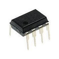
ATTINY12L-4PU Atmel, ATTINY12L-4PU Datasheet - Page 49

ATTINY12L-4PU
Manufacturer Part Number
ATTINY12L-4PU
Description
MCU 8-Bit ATtiny AVR RISC 1KB Flash 3.3V/5V 8-Pin PDIP
Manufacturer
Atmel
Datasheet
1.ATTINY12V-1SI.pdf
(94 pages)
Specifications of ATTINY12L-4PU
Package
8PDIP
Device Core
AVR
Family Name
ATtiny
Maximum Speed
4 MHz
Operating Supply Voltage
3.3|5 V
Data Bus Width
8 Bit
Number Of Programmable I/os
6
Interface Type
SPI
Number Of Timers
1
Program Memory Size
1 KB
Program Memory Type
Flash
Operating Temperature
-40 to 85 °C
Processor Series
ATTINY1x
Core
AVR8
Maximum Clock Frequency
4 MHz
Maximum Operating Temperature
+ 85 C
Mounting Style
Through Hole
Package / Case
PDIP-8
3rd Party Development Tools
EWAVR, EWAVR-BL
Development Tools By Supplier
ATAVRDRAGON, ATSTK500
Minimum Operating Temperature
- 40 C
Lead Free Status / Rohs Status
Details
Signature Bytes
Calibration Byte in
ATtiny12
Programming the Flash
and EEPROM
ATtiny11
ATtiny12
1006F–AVR–06/07
•
The status of the fuse bits is not affected by Chip Erase.
Note:
All Atmel microcontrollers have a three-byte signature code which identifies the device.
The three bytes reside in a separate address space.
For the ATtiny11 they are:
1. $000: $1E (indicates manufactured by Atmel)
2. $001: $90 (indicates 1 Kb Flash memory)
3. $002: $04 (indicates ATtiny11 device when signature byte $001 is $90)
For the ATtiny12
1. $000: $1E (indicates manufactured by Atmel)
2. $001: $90 (indicates 1 Kb Flash memory)
3. $002: $05 (indicates ATtiny12 device when signature byte $001 is $90)
Note:
The ATtiny12 has a one-byte calibration value for the internal RC oscillator. This byte
resides in the high byte of address $000 in the signature address space. During memory
programming, the external programmer must read this location and program its value
into a selected location in the normal Flash or EEPROM Program memory. At start-up,
the user software must read this Flash location and write the value to the OSCCAL
register.
Atmel’s ATtiny11 offers 1K bytes of Flash Program memory.
The ATtiny11 is shipped with the on-chip Flash Program memory array in the erased
state (i.e., contents = $FF) and ready to be programmed.
This device supports a High-voltage (12V) Serial programming mode. Only minor cur-
rents (<1 mA) are drawn from the +12V pin during programming.
The program memory array in the ATtiny11 is programmed byte-by-byte.
Atmel’s ATtiny12 offers 1K bytes of in-system reprogrammable Flash Program memory
and 64 bytes of in-system reprogrammable EEPROM Data memory.
The ATtiny12 is shipped with the on-chip Flash Program and EEPROM Data memory
arrays in the erased state (i.e., contents = $FF) and ready to be programmed.
This device supports a high-voltage (12V) serial programming mode and a low-voltage
serial programming mode. The +12V is used for programming enable only, and no cur-
rent of significance is drawn by this pin. The Low-voltage Serial Programming mode
CKSEL3..0 fuses: See Table 3, “Device Clocking Options Select,” on page 10 and
Table 10, “ATtiny12 Clock Options and Start-up Times,” on page 25, for which
combination of CKSEL3..0 to use. Default value is “0010”, internal RC oscillator with
long start-up time.
1. If the RSTDISBL Fuse is programmed, then the programming hardware should apply
1. When both lock bits are programmed (Lock mode 3), the Signature Bytes can not be
+12V to PB5 while the ATtiny12 is in Power-on Reset. If not, the part can fail to enter
programming mode caused by drive contention on PB0 and/or PB5.
read in the Low-voltage Serial mode. Reading the Signature Bytes will return: $00,
$01 and $02.
(1)
they are:
ATtiny11/12
49


