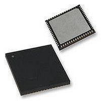
PIC24FJ64GA106-E/MR Microchip Technology, PIC24FJ64GA106-E/MR Datasheet - Page 25

PIC24FJ64GA106-E/MR
Manufacturer Part Number
PIC24FJ64GA106-E/MR
Description
16-bit, 16 MIPS, 64KB Flash, 16Kb RAM, 84 I/O, NanoWatt 64 QFN 9x9x0.9mm TUBE
Manufacturer
Microchip Technology
Series
PIC® 24Fr
Datasheet
1.PIC24FJ128GA106-IPT.pdf
(330 pages)
Specifications of PIC24FJ64GA106-E/MR
Core Processor
PIC
Core Size
16-Bit
Speed
32MHz
Connectivity
I²C, IrDA, LIN, SPI, UART/USART
Peripherals
Brown-out Detect/Reset, LVD, POR, PWM, WDT
Number Of I /o
53
Program Memory Size
64KB (22K x 24)
Program Memory Type
FLASH
Ram Size
16K x 8
Voltage - Supply (vcc/vdd)
2 V ~ 3.6 V
Data Converters
A/D 16x10b
Oscillator Type
Internal
Operating Temperature
-40°C ~ 125°C
Package / Case
*
Processor Series
PIC24FJ256GA110
Core
PIC
Data Bus Width
16 bit
Data Ram Size
16 KB
Interface Type
UART, I2C, SPI
Maximum Clock Frequency
8 MHz
Number Of Timers
5
Operating Supply Voltage
3.6 V
Maximum Operating Temperature
- 40 C to + 85 C
Mounting Style
SMD/SMT
Lead Free Status / RoHS Status
Lead free / RoHS Compliant
Eeprom Size
-
Lead Free Status / Rohs Status
Details
- Current page: 25 of 330
- Download datasheet (3Mb)
2.4
The on-chip voltage regulator enable/disable pin
(ENVREG or DISVREG, depending on the device
family) must always be connected directly to either a
supply voltage or to ground. The particular connection
is determined by whether or not the regulator is to be
used:
• For ENVREG, tie to V
• For DISVREG, tie to ground to enable the
Refer to
for details on connecting and using the on-chip
regulator.
When the regulator is enabled, a low-ESR (< 5Ω)
capacitor is required on the V
stabilize the voltage regulator output voltage. The
V
must use a capacitor of 10 µF connected to ground. The
type can be ceramic or tantalum. Suitable examples of
capacitors are shown in
equivalent specification can be used.
TABLE 2-1:
2010 Microchip Technology Inc.
CAP
Note:
or to ground to disable the regulator
regulator or to V
Panasonic
Panasonic
Murata
Murata
Make
/V
TDK
TDK
DDCORE
Voltage Regulator Pins
(ENVREG/DISVREG and
V
Section 25.2 “On-Chip Voltage Regulator”
CAP
This section applies only to PIC24F J
devices with an on-chip voltage regulator.
/V
pin must not be connected to V
SUITABLE CAPACITOR EQUIVALENTS
DDCORE
GRM32DR71C106KA01L
GRM31CR61C106KC31L
DD
to disable the regulator
C3216X7R1C106K
C3216X5R1C106K
ECJ-3YX1C106K
ECJ-4YB1C106K
DD
to enable the regulator,
Table
)
Part #
CAP
2-1. Capacitors with
/V
DDCORE
PIC24FJ256GA110 FAMILY
DD
pin to
Capacitance
and
Nominal
10 µF
10 µF
10 µF
10 µF
10 µF
10 µF
Designers may use
equivalence of candidate devices.
The placement of this capacitor should be close to
V
length not exceed 0.25 inch (6 mm). Refer to
Section 28.0
additional information.
When the regulator is disabled, the V
must be tied to a voltage supply at the V
Refer to
information on V
FIGURE 2-3:
.
CAP
Base Tolerance Rated Voltage Temp. Range
0.001
Note:
0.01
0.1
/V
10
1
DDCORE
0.01
±10%
±10%
±10%
±10%
±10%
±10%
Section 28.0 “Electrical Characteristics”
Typical data measurement at 25°C, 0V DC bias.
. It is recommended that the trace
0.1
DD
“Electrical
and V
Frequency (MHz)
FREQUENCY vs. ESR
PERFORMANCE FOR
SUGGESTED V
1
Figure 2-3
DDCORE
16V
16V
16V
16V
16V
16V
10
Characteristics”
.
to evaluate ESR
100
DS39905E-page 25
CAP
-55 to 125ºC
-55 to 125ºC
-55 to 125ºC
-55 to 85ºC
-55 to 85ºC
-55 to 85ºC
DDCORE
/V
CAP
1000 10,000
DDCORE
level.
pin
for
for
Related parts for PIC24FJ64GA106-E/MR
Image
Part Number
Description
Manufacturer
Datasheet
Request
R

Part Number:
Description:
Manufacturer:
Microchip Technology Inc.
Datasheet:

Part Number:
Description:
Manufacturer:
Microchip Technology Inc.
Datasheet:

Part Number:
Description:
Manufacturer:
Microchip Technology Inc.
Datasheet:

Part Number:
Description:
Manufacturer:
Microchip Technology Inc.
Datasheet:

Part Number:
Description:
Manufacturer:
Microchip Technology Inc.
Datasheet:

Part Number:
Description:
Manufacturer:
Microchip Technology Inc.
Datasheet:

Part Number:
Description:
Manufacturer:
Microchip Technology Inc.
Datasheet:

Part Number:
Description:
Manufacturer:
Microchip Technology Inc.
Datasheet:


