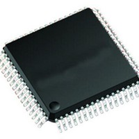
PIC24FJ64GA106T-I/PT Microchip Technology, PIC24FJ64GA106T-I/PT Datasheet - Page 69

PIC24FJ64GA106T-I/PT
Manufacturer Part Number
PIC24FJ64GA106T-I/PT
Description
16-bit, 16 MIPS, 64KB Flash, 16Kb RAM, 84 I/O, NanoWatt 64 TQFP 10x10x1mm T/R
Manufacturer
Microchip Technology
Series
PIC® 24Fr
Datasheet
1.PIC24FJ128GA106-IPT.pdf
(330 pages)
Specifications of PIC24FJ64GA106T-I/PT
Core Processor
PIC
Core Size
16-Bit
Speed
32MHz
Connectivity
I²C, IrDA, LIN, SPI, UART/USART
Peripherals
Brown-out Detect/Reset, LVD, POR, PWM, WDT
Number Of I /o
53
Program Memory Size
64KB (22K x 24)
Program Memory Type
FLASH
Ram Size
16K x 8
Voltage - Supply (vcc/vdd)
2 V ~ 3.6 V
Data Converters
A/D 16x10b
Oscillator Type
Internal
Operating Temperature
-40°C ~ 85°C
Package / Case
*
Processor Series
PIC24FJ256GA110
Core
PIC
Data Bus Width
16 bit
Data Ram Size
16 KB
Interface Type
UART, I2C, SPI
Maximum Clock Frequency
8 MHz
Number Of Timers
5
Operating Supply Voltage
3.6 V
Maximum Operating Temperature
- 40 C to + 85 C
Mounting Style
SMD/SMT
Lead Free Status / RoHS Status
Lead free / RoHS Compliant
Eeprom Size
-
Lead Free Status / Rohs Status
Details
Available stocks
Company
Part Number
Manufacturer
Quantity
Price
Company:
Part Number:
PIC24FJ64GA106T-I/PT
Manufacturer:
Microchip Technology
Quantity:
10 000
- Current page: 69 of 330
- Download datasheet (3Mb)
6.2.1
The oscillator start-up circuitry and its associated delay
timers are not linked to the device Reset delays that
occur at power-up. Some crystal circuits (especially
low-frequency crystals) will have a relatively long
start-up time. Therefore, one or more of the following
conditions is possible after SYSRST is released:
• The oscillator circuit has not begun to oscillate.
• The Oscillator Start-up Timer has not expired (if a
• The PLL has not achieved a lock (if PLL is used).
The device will not begin to execute code until a valid
clock source has been released to the system. There-
fore, the oscillator and PLL start-up delays must be
considered when the Reset delay time must be known.
6.2.2
If the FSCM is enabled, it will begin to monitor the
system clock source when SYSRST is released. If a
valid clock source is not available at this time, the
device will automatically switch to the FRC Oscillator
and the user can switch to the desired crystal oscillator
in the Trap Service Routine (TSR).
2010 Microchip Technology Inc.
crystal oscillator is used).
POR AND LONG OSCILLATOR
START-UP TIMES
FAIL-SAFE CLOCK MONITOR
(FSCM) AND DEVICE RESETS
PIC24FJ256GA110 FAMILY
6.3
Most of the Special Function Registers (SFRs) associ-
ated with the PIC24F CPU and peripherals are reset to a
particular value at a device Reset. The SFRs are
grouped by their peripheral or CPU function and their
Reset values are specified in each section of this manual.
The Reset value for each SFR does not depend on the
type of Reset with the exception of four registers. The
Reset value for the Reset Control register, RCON, will
depend on the type of device Reset. The Reset value
for the Oscillator Control register, OSCCON, will
depend on the type of Reset and the programmed
values of the FNOSC bits in Flash Configuration
Word 2 (CW2); see
NVMCON registers are only affected by a POR.
Special Function Register Reset
States
Table
6-2. The RCFGCAL and
DS39905E-page 69
Related parts for PIC24FJ64GA106T-I/PT
Image
Part Number
Description
Manufacturer
Datasheet
Request
R

Part Number:
Description:
Manufacturer:
Microchip Technology Inc.
Datasheet:

Part Number:
Description:
Manufacturer:
Microchip Technology Inc.
Datasheet:

Part Number:
Description:
Manufacturer:
Microchip Technology Inc.
Datasheet:

Part Number:
Description:
Manufacturer:
Microchip Technology Inc.
Datasheet:

Part Number:
Description:
Manufacturer:
Microchip Technology Inc.
Datasheet:

Part Number:
Description:
Manufacturer:
Microchip Technology Inc.
Datasheet:

Part Number:
Description:
Manufacturer:
Microchip Technology Inc.
Datasheet:

Part Number:
Description:
Manufacturer:
Microchip Technology Inc.
Datasheet:


