CUB4TC00 Red Lion Controls, CUB4TC00 Datasheet - Page 2
CUB4TC00
Manufacturer Part Number
CUB4TC00
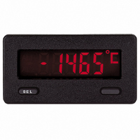
Description
METER PANEL LCD THERMOCOUPLE
Manufacturer
Red Lion Controls
Series
CUB4r
Type
Thermocoupler
Datasheet
1.CUB4TC00.pdf
(8 pages)
Specifications of CUB4TC00
Display Type
LCD Non-Backlit
Display Face Size
2.95" L x 1.54" W (74.9 x 39.1mm)
Display Digits
5
Display Digits - Height
0.480" (12.19mm)
Backlight
Without
Mounting Type
Panel Mount
Termination
Screw Terminals
Voltage - Supply
9 V ~ 26 V
Applications
Thermocouple Input - Type T, E, J, K, R, S, B, N, or mV
Number Of Digits/alpha
5
Lead Free Status / RoHS Status
Lead free / RoHS Compliant
Other names
Q1421239
Q763911
Q763911


EMC INSTALLATION GUIDELINES
ElectroMagnetic Interference (EMI), proper installation and wiring methods
must be followed to ensure compatibility in each application. The type of the
electrical noise, source or coupling method into the unit may be different for
various installations. In extremely high EMI environments, additional measures
may be needed. The unit becomes more immune to EMI with fewer I/O
connections. Cable length, routing and shield termination are very important and
can mean the difference between a successful or a troublesome installation.
Listed below are some EMC guidelines for successful installation in an
industrial environment.
1. The unit should be mounted in a metal enclosure, that is properly connected
2. Use shielded (screened) cables for all Signal and Control inputs. The shield
3. Never run Signal or Control cables in the same conduit or raceway with AC
SPECIFICATIONS (Cont’d)
CUB4TC Thermocouple Inputs:
CUB4RT RTD Inputs:
* After 20 min. warm-up. Accuracy specified for the 0 to 50°C operating range
TYPE
Cu427
mV
Pt392
Pt385
Ni672
Although this unit is designed with a high degree of immunity to
to protective earth.
(screen) pigtail connection should be made as short as possible. The
connection point for the shield depends somewhat upon the application.
Listed below are the recommended methods of connecting the shield, in order
of their effectiveness.
a. Connect the shield to earth ground (protective earth) only at the panel
b. Connect the shield to earth ground at both ends of the cable, usually when
c. Connect the shield to common of the unit and leave the other end of the
power lines, conductors feeding motors, solenoids, SCR controls, and
heaters, etc. The cables should be run in metal conduit that is properly
TC
Input Impedance: 20 M
Lead Resistance Effect: 0.03µV/ohm
Maximum Input Voltage: 30 VDC, TC+ to TC-
Maximum Input Voltage TC-: 3 VDC max. with respect to common
Lead Resistance:
Balanced Lead Resistance: Automatically compensated up to max per lead.
Unbalanced Lead Resistance: uncompensated
includes meter temperature coefficient and ice point tracking effects (TC
only.) The accuracy specifications includes the A/D conversion errors,
linearization conformity, and thermocouple ice point compensation (TC
only.) Total system accuracy is the sum of the meter and probe errors.
Accuracy may be improved by field calibrating the meter readout at the
temperature of interest.
Type
R
N
T
K
S
B
E
J
where the unit is mounted.
the noise source frequency is above 1 MHz.
shield unconnected and insulated from earth ground.
Cu427: 3 ohms/lead, 6 ohms total
All others: 10 ohms/lead, 20 ohms total
DISPLAY
Jumper Position
LIN
t
K
J
r
S
b
E
n
(See Wiring
Diagram)
B
B
B
A
-200 to 1372°C
-328 to 2502°F
-328 to 1400°F
-328 to 1448°F
-200 to 1300°C
-328 to 2372°F
-10.00 to 60.00
200 to 1820°C
300 to 3308°F
-200 to 400°C
-200 to 760°C
-200 to 787°C
-328 to 752°F
32 to 3214°F
32 to 3214°F
0 to 1768°C
0 to 1768°C
RANGE
9.035 Ohm
100 Ohm
100 Ohm
120 Ohm
Nominal
@ 0°C
ACCURACY*
9.1<540
4.5>540
0.02 mV
@ 23°C
±°C
2.3
2.3
1.9
4.5
4.5
2.7
2.8
-200 to 850
-200 to 850
-100 to 260
-80 to 260
Range
°C
°C
ACCURACY*
42.6<540
15.0>540
@ 0 to 50°C
0.08 mV
15.0
15.0
±°C
5.8
5.8
4.3
4.9
8.1
Accuracy *
@ 23°C
±1LSD
°C
°C
0.7 C
0.7 C
0.7 C
0.9 C
ORANGE ORANGE
YELLOW BROWN
VIOLET
BLACK
BLACK
WHITE
GREY
BLUE
ANSI
N/A
WIRE COLOR
Accuracy *
@ 0 to 50°C
±1LSD
YELLOW
2.7 C
BROWN
2.7 C
1.5 C
1.7 C
BS 1843
WHITE
WHITE
WHITE
NONE
N/A
2
7. CERTIFICATIONS AND COMPLIANCES:
8. CONNECTION: Wire clamping screw terminals.
9. CONSTRUCTION: High impact plastic case with clear viewing window.
10. WEIGHT: 3.3 oz. (93.5 g)
4. Signal or Control cables within an enclosure should be routed as far away as
5. In extremely high EMI environments, the use of external EMI suppression
6. Long cable runs are more susceptible to EMI pickup than short cable runs.
SAFETY
UL Recognized Component, File # E179259, UL3101-1, CSA 22.2 No. 1010-1
Type 4X Enclosure rating (Face only), UL50
IECEE CB Scheme Test Certificate #UL2356A-179259/USA,
ELECTROMAGNETIC COMPATIBILITY
Notes:
(Panel gasket and mounting clips included.) Unit is rated for NEMA 4X/IP65
indoor use. Installation Category I, Pollution Degree 2.
grounded. This is especially useful in applications where cable runs are long
and portable two-way radios are used in close proximity, or if the installation
is near a commercial radio transmitter.
possible from contactors, control relays, transformers, and other noisy
components.
devices, such as ferrite suppression cores, is effective. Install them on Signal
and Control cables as close to the unit as possible. Loop the cable through the
core several times or use multiple cores on each cable for additional protection.
Install line filters on the power input cable to the unit to suppress power line
interference. Install them near the power entry point of the enclosure. The
following EMI suppression devices (or equivalent) are recommended:
Ferrite Suppression Cores for signal and control cables:
Line Filters for input power cables:
Note: Reference manufacturer’s instructions when installing a line filter.
Therefore, keep cable runs as short as possible.
Immunity to EN 50082-2
Electrostatic discharge
Electromagnetic RF fields
Fast transients (burst)
RF conducted interference
Simulation of cordless telephone
Emissions to EN 50081-1
RF interference
Recognized to U.S. and Canadian requirements under the Component
Recognition Program of Underwriters Laboratories, Inc.
CB Scheme Test Report #98ME60090-000098
IEC 1010-1, EN 61010-1: Safety requirements for electrical equipment
IP65 Enclosure rating (Face only), IEC 529
1. Self-recoverable loss of performance during EMI disturbance at 10 V/m:
2. Self-recoverable loss of performance during EMI disturbance at 10 Vrms:
Refer to EMC Installation Guidelines section of the bulletin for additional
Fair-Rite # 0443167251 (RLC #FCOR0000)
TDK # ZCAT3035-1330A
Steward #28B2029-0A0
Schaffner # FN610-1/07 (RLC #LFIL0000)
Schaffner # FN670-1.8/07
Corcom #1VR3
Issued by Underwriters Laboratories Inc.
for measurement, control and laboratory use, Part 1.
For operation without loss of performance:
For operation without loss of performance:
information.
Process signal may deviate during EMI disturbance.
Unit is panel mounted in a metal enclosure (Buckeye SM7013-0 or
I/O cables routed in metal conduit connected to earth ground.
Process signal may deviate during EMI disturbance.
Install power line filter, RLC#LFIL0000 or equivalent, at the unit.
equivalent).
EN 61000-4-2
EN 61000-4-3
EN 61000-4-4
EN 61000-4-6
ENV 50204
EN 55022
Level 2; 4 Kv contact
Level 3; 8 Kv air
Level 3; 10 V/m
80 MHz - 1 GHz
Level 4; 2 Kv I/O
Level 3; 2 Kv power
Level 3; 10 V/rms
150 KHz - 80 MHz
Level 3; 10 V/m
900 MHz ± 5 MHz
200 Hz, 50% duty cycle
Enclosure class B
1
2