CUB4TC00 Red Lion Controls, CUB4TC00 Datasheet - Page 3
CUB4TC00
Manufacturer Part Number
CUB4TC00
Description
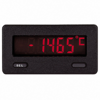
METER PANEL LCD THERMOCOUPLE
Manufacturer
Red Lion Controls
Series
CUB4r
Type
Thermocoupler
Datasheet
1.CUB4TC00.pdf
(8 pages)
Specifications of CUB4TC00
Display Type
LCD Non-Backlit
Display Face Size
2.95" L x 1.54" W (74.9 x 39.1mm)
Display Digits
5
Display Digits - Height
0.480" (12.19mm)
Backlight
Without
Mounting Type
Panel Mount
Termination
Screw Terminals
Voltage - Supply
9 V ~ 26 V
Applications
Thermocouple Input - Type T, E, J, K, R, S, B, N, or mV
Number Of Digits/alpha
5
Lead Free Status / RoHS Status
Lead free / RoHS Compliant
Other names
Q1421239
Q763911
Q763911


WIRING CONNECTIONS
cabling should conform to appropriate standards of good installation, local
codes and regulations. It is recommended that power supplied to the unit be
protected by a fuse or circuit breaker.
drafts and areas subject to radical temperature shifts.
CUB4RT WIRING
Electrical
shown in the wiring diagram. Place jumper in appropriate position.
length, gauge, and material. Keep wire length to a minimum. Do not run RTD
signal wires with Class 1 wiring.
observing the correct polarity. If more than one CUB4RT are powered from the
same supply, the probes must be isolated from each other. Normal operation
does not require use of the PROG terminal. However, a switch may be installed
between PROG (#4) and COMM (#1) if desired.
CUB4TC WIRING
Electrical
the correct polarity. Keep wire length to a minimum to reduce lead resistance
errors. Do not run thermocouple wires with Class 1 wiring.
observing the correct polarity. If more than one CUB4TC are powered from the
same supply, the probes must be isolated from each other.
terminal (#5), as erroneous readings will result. Also be aware when using
grounded thermocouple probes that the probes’ protective sheath is electrically
connected to the measuring junction. If the protective sheath is connected to the
power supply common, this will connect terminals 1 and 5 together, which may
result in erroneous readings.
All conductors should meet voltage and current ratings of the unit. Also,
Unit should be mounted in a relatively stable temperature environment. Avoid
Connect RTD wires to Terminals EXC (#6), SIG+ (#3) and SIG- (#5) as
To minimize lead resistance effects, the three RTD wires should be the same
Connect the 9 to 26 VDC power to terminals VDC (#2) and COMM (#1),
Connect thermocouple wires to terminals TC+(#3) and TC-(#5), observing
Connect the 9 to 26 VDC power to terminals VDC(#2) and COMM(#1),
Note: Do not connect the power supply COMM terminal (#1) to the TC-
CAUTION: To maintain the SELV rating of the CUB4TC, the
thermocouple probe should be isolated from any accidental
contact with hazardous voltage or non-SELV circuitry.
Jumper Positions
3
BASIC OPERATION
begin a power up sequence that displays the version of the software and any
diagnostic messages. After approximately four seconds, the unit will begin to
display the temperature of the sensor or the millivolt input, depending upon
input type selected.
indicates that the stored programming and/or calibration values may have
become corrupted. Pressing the “SEL” button will remove the current message
from the display.
be pressed to display the type of input the unit has been programmed to display.
The display will return to normal indication after three seconds.
DIAGNOSTIC MESSAGES
FAIL
FLPrG
FLCAL
PROGRAMMING
the Program Menu of the meter is accomplished by electrically connecting the
PROGRAM terminal to the COMM terminal with a wire or a switch.
Program Menu is accomplished by disconnecting the electrical connection
between the PROGRAM terminal and the COMM terminal. During exit of
programming, the unit displays
written to non-volatile memory.
removed from the meter during exit of the Program Menu, data may not be
saved completely or correctly, and may cause a
the next power-up cycle. If power is removed before exiting the Program Menu,
all changes (including calibration information) will be lost and previous values
will be used upon power-up.
traverse the Programming Menu and to select values for the corresponding
Programming Menu Items.
PROGRAM MENU - Selection Variables
typE-pt392
input types. Press “SEL” button to enter the choice and return to the main menu.
tYPE
input types. Press the “SEL” button to enter the choice and return to the main
menu.
CJC
Normal operation begins with application of power to the meter. The unit will
A diagnostic message of
Once the unit is displaying temperature or millivolts, the “SEL” button may
must acknowledge this message by pressing the “SEL” button before
proceeding to normal operation. Once the unit is in normal operation, the
messages
remain active even if power is removed and reapplied, until the unit is
reprogrammed. If the message appears on next power up after the unit has
been reprogrammed, it may indicate a nonfunctional memory component.
to calculate the display value. This flashing display will remain active even if
power is removed and reapplied, until the unit is recalibrated. If the message
appears on next power up after the unit has been recalibrated, it may indicate
a nonfunctional memory component. The nominal values used to calculate
the input signal value may cause indication errors of up to 10% of full scale.
The unit should be recalibrated to restore normal display accuracy as soon as
possible.
Programming may be entered at any time during normal operation. Entering
Programming may be exited at any time except during calibration. Exiting the
All programming data is stored upon exit of programming. If power is
Programming the meter involves using the “SEL” and “blank” buttons to
SEL: Steps to next Program Menu selection.
Blank: Scrolls through selection variables and enters into programming for
To select the input type, press the blank button to scroll through the available
To select the input type, press the blank button to scroll through the available
This program item enables or disables internal cold junction compensation.
Pressing the “blank” button toggles between Yes and No.
For most applications, cold junction compensation should be enabled (
Press the “SEL” button to enter the choice and return to the main menu.
This menu item does not appear if
the selected value.
-
- indicates that a non-volatile memory fault has occurred. The operator
- indicates that calibration data is corrupt and nominal values will be used
- indicates that non-calibration data is corrupt. This flashing display will
-
YES
t
,
E
,
FLPrG
,
NO
J
,
,
pt385
K
(CUB4TC Only)
and or
,
r
,
S
,
FLCAL
,
Ni672
b
,
FAIL
n
SAVE
will be periodically flashed on the display.
, or
,
may occur on power up. This message
Cu427
to indicate that the data is currently being
tYPE
LIN
=
(CUB4TC Only)
LIN
(CUB4RT Only)
FAIL
.
message to occur during
yES
).