CUB4TC00 Red Lion Controls, CUB4TC00 Datasheet - Page 5
CUB4TC00
Manufacturer Part Number
CUB4TC00
Description
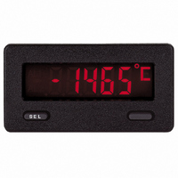
METER PANEL LCD THERMOCOUPLE
Manufacturer
Red Lion Controls
Series
CUB4r
Type
Thermocoupler
Datasheet
1.CUB4TC00.pdf
(8 pages)
Specifications of CUB4TC00
Display Type
LCD Non-Backlit
Display Face Size
2.95" L x 1.54" W (74.9 x 39.1mm)
Display Digits
5
Display Digits - Height
0.480" (12.19mm)
Backlight
Without
Mounting Type
Panel Mount
Termination
Screw Terminals
Voltage - Supply
9 V ~ 26 V
Applications
Thermocouple Input - Type T, E, J, K, R, S, B, N, or mV
Number Of Digits/alpha
5
Lead Free Status / RoHS Status
Lead free / RoHS Compliant
Other names
Q1421239
Q763911
Q763911


CALIBRATING THE CUB4TC
values to provide accurate temperature and voltage measurements. Over time,
the electrical characteristics of the components inside the CUB4TC will slowly
change with the result that the stored calibration values no longer accurately
define the input circuit. For most applications, recalibration every 1 to 2 years
should be sufficient.
calibration. It is recommended that both calibrations be performed. The voltage
calibration MUST precede the cold junction calibration. Allow 30 minute warm-
up before performing any calibration related procedure. The following
procedures should be performed at an ambient temperature of 15 to 35 °C (59 to
95 °F).
calibrating electronic equipment.
CAUTION: The accuracy of the calibration equipment will directly affect the
Voltage Calibration Check
1. Enter the programming menu and set
2. Use a precision DC voltage supply with an accuracy of 0.03% or better.
1. Connect a precision Voltage Source with an output range of 0.000 to 105.000
2. Enter the Program Menu and step through the Program Menu list by pressing
3. Press the “blank” button to change
4. The display shows
5. After entering the correct access code, the unit will display
6. After voltage calibration is complete, the display will show
7. Place the input selector jumper in position ‘B’.
8. Connect a precision resistance decade box with an accuracy of
9. With the display showing
mV DISPLAY
The CUB4TC uses stored voltage calibration and cold junction temperature
Calibration of the CUB4TC involves a voltage calibration and a cold junction
Calibration should only be performed by individuals experienced in
accuracy of the CUB4TC.
programming.
Connect the negative lead of the power supply to TC- (#5) and the positive
lead of the power supply to TC+ (#3).
mV and an accuracy of 0.03% or better to the SIG+ (#3) and SIG- (#5)
terminals. Placement of jumper does not affect voltage calibration.
the “SEL” button until
code to
table below for calibration sequence.The unit displays
seconds after pressing the “SEL” button before proceeding to the next input
point.
to the unit as a three wire RTD. See Resistance Calibration Diagram.
the “SEL” button. The unit displays
display will change to
IN1
IN2
IN3
IN4
IN5
IN6
IN7
IN8
00006.
Press and hold “SEL”.
PARAMETER
105.000 mV
15.000 mV
30.000 mV
45.000 mV
60.000 mV
75.000 mV
90.000 mV
0.000 mV
00000.
Voltage Calibration Diagram
r 0
CAL
r 200
.
is displayed.
Use the “blank” button to increment the access
, set the resistance to 200 ohms, then press
Apply 105.000 mV, wait 5 sec., press
Apply 15.000 mV, wait 5 sec., press
Apply 30.000 mV, wait 5 sec., press
Apply 45.000 mV, wait 5 sec., press
Apply 60.000 mV, wait 5 sec., press
Apply 75.000 mV, wait 5 sec., press
Apply 90.000 mV, wait 5 sec., press
no
Apply 0.000 mV, wait 5 sec., press
CALC
to
tYPE
YES
for a few seconds and then the
. Press “SEL”.
to
LIN
ACTION
and
CALC
OFSEt
r 200
IN1
. Follow the
for about 3
0.01 ohms
to
.
0
SEL
SEL
SEL
SEL
SEL
SEL
SEL
. Exit
SEL
5
10. With the display showing
11. With the display showing
12. Change the input selector jumper to position ‘A’.
13. With the display showing
14. With the display showing
15. With the display showing
Before exiting the programming menu, verify that the
Entering code
3. Compare the CUB4TC read-out to the precision DC supply at various points
4. Calibrate the CUB4TC if the readings are out of tolerance.
Cold Junction Calibration Check
1. Enter Programming Menu, and verify the following:
2. Connect a thermocouple probe of known accuracy and type (J, K, E, T, or N)
3. Connect a reference temperature probe to measuring end of thermocouple to
4. Compare unit display with reference temperature indicator. The unit display
5. Calibrate the cold junction temperature if out of tolerance.
“SEL” button. The unit displays
will change to
the “SEL” button. The unit displays
display will change to
“SEL” button. The unit displays
will change to
“SEL” button. The unit displays
will change to
“SEL” button. The unit displays
will return to the
type and the input selector jumper is in the appropriate position. Exit
programming and check the calibration. Repeat if necessary
mode is for diagnostic purposes only. When power is removed from the
CUB4RT, the display will return to its previously programmed state. If the
RTD type is set for
read
B, will cause the display to read
over the range (–10.00 mVDC to 60.00 mVDC). The tolerance is ± 2 LSD
(±0.02 mV), at all points within this range.
Make any necessary changes to programming.
to the CUB4TC. The probe should match the one selected in programming.
monitor temperature. Allow sufficient time for temperatures to equalize (at
least 15 minutes).
should equal the reference probe temperature. Tolerance is ±1.0 °C.
00. 0 00
to
85
20. 0 00
r 400
r 0
r 20
will place the CUB4RT in a resistance display mode. This
CAL
.
Cu427
OFSEt
.
Resistance Calibration Diagram
tyPE
dISP
.
program item.
ohms. All other RTD types with the jumper in position
CJC
r 10
and the jumper is set to position A, the display will
r 10
r 20
= probe being connected to the unit.
=
=
=
r 400
r 0
r 0
.
YES
0. 0 °C
0
, set the resistance to 0 ohms, then press the
, set the resistance to 0 ohms, then press the
, set the resistance to 10 ohms, then press the
, set the resistance to 20 ohms, then press the
CALC
CALC
CALC
000. 0 0
CALC
, set the resistance to 400 ohms, then press
CALC
for a few seconds and then the display
for a few seconds and then the display
for a few seconds and then the display
for a few seconds and then the unit
to
400. 0 0
for a few seconds and then the
ohms
tyPE
is set to the desired