DP8572AN National Semiconductor, DP8572AN Datasheet - Page 17
DP8572AN
Manufacturer Part Number
DP8572AN
Description
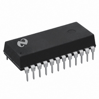
IC REAL TIME CLOCK W/RAM 24 DIP
Manufacturer
National Semiconductor
Type
Clock/Calendar/NVSRAMr
Datasheet
1.DP8572AN.pdf
(22 pages)
Specifications of DP8572AN
Memory Size
44B
Time Format
HH:MM:SS:hh (12/24 hr)
Date Format
YY-MM-DD-dd
Interface
Parallel
Voltage - Supply
4.5 V ~ 5.5 V
Operating Temperature
-40°C ~ 85°C
Mounting Type
Through Hole
Package / Case
24-DIP (0.300", 7.62mm)
Lead Free Status / RoHS Status
Contains lead / RoHS non-compliant
Other names
*DP8572AN
DP8572
DP8572
Available stocks
Company
Part Number
Manufacturer
Quantity
Price

Part Number:
DP8572AN
Manufacturer:
TOSHIBA/东芝
Quantity:
20 000


Functional Description
D7 This bit is used to program the signal appearing at the
MFO output as follows
INTERRUPT CONTROL REGISTER 0
D0 –D5 These bits are used to enable one of the selected
periodic interrupts by writing a one into the appropriate bit
These interrupts are issued at the rollover of the clock For
example the minutes interrupt will be issued whenever the
minutes counter increments In all likelihood the interrupt
will be enabled asynchronously with the real time change
Therefore the very first interrupt will occur in less than the
periodic time chosen but after the first interrupt all subse-
quent interrupts will be spaced correctly These interrupts
are useful when minute second real time reading or task
switching is required When all six bits are written to a 0 this
disables periodic interrupts from the Main Status Register
and the interrupt pin If a battery backed mode is selected
and the DP8572A is in standby (V
are controlled by D4 of the Real Time Mode Register
D6 and D7 General Purpose RAM
D7
0
1
Power Fail Interrupt
Buffered Crystal Oscillator
MFO Output Signal
BB l
(Continued)
V
CC
) then these bits
TL F 9980 – 17
17
INTERRUPT CONTROL REGISTER 1
D0– D5 Each of these bits are enable bits which will enable
a comparison between an individual clock counter and its
associated compare RAM If any bit is a zero then that
clock-RAM comparator is set to the ‘‘always equal’’ state
and the associated TIME COMPARE RAM byte can be used
as general purpose RAM However to ensure that an alarm
interrupt is not generated at bit D3 of the Main Status Regis-
ter all bits must be written to a logic zero
D6 In order to generate an external alarm compare inter-
rupt to the P from bit D3 of the Main Status Register this
bit must be written to a logic 1 If a battery backed mode is
selected and the DP8572A is in standby (V
this bit is controlled by D4 of the Real Time Mode Register
D7 The MSB of this register is the enable bit for the Power
Fail Interrupt When this bit is set to a one an interrupt will
be generated to the
backed mode is selected and the DP8572A is in standby
(V
Time Mode Register
This bit also enables the low battery detection analog cir-
cuitry
BB l
V
CC
) then this bit is controlled by D4 of the Real
P when V
BB l
V
BB l
CC
If a battery
TL F 9980 – 18
V
CC
) then
Related parts for DP8572AN
Image
Part Number
Description
Manufacturer
Datasheet
Request
R

Part Number:
Description:
National Semiconductor [8-Bit D/A Converter]
Manufacturer:
National Semiconductor
Datasheet:
Part Number:
Description:
National Semiconductor [Media Coprocessor]
Manufacturer:
National Semiconductor
Datasheet:
Part Number:
Description:
Digitally Controlled Tone and Volume Circuit with Stereo Audio Power Amplifier, Microphone Preamp Stage and National 3D Sound
Manufacturer:
National Semiconductor
Datasheet:
Part Number:
Description:
Digitally Controlled Tone and Volume Circuit with Stereo Audio Power Amplifier, Microphone Preamp Stage and National 3D Sound
Manufacturer:
National Semiconductor
Datasheet:
Part Number:
Description:
AC97 Rev 2 Codec with Sample Rate Conversion and National 3D Sound
Manufacturer:
National Semiconductor
Part Number:
Description:
Manufacturer:
National Semiconductor
Datasheet:
Part Number:
Description:
Manufacturer:
National Semiconductor
Datasheet:
Part Number:
Description:
General Purpose, Low Voltage, Low Power, Rail-to-Rail Output Operational Amplifiers
Manufacturer:
National Semiconductor
Datasheet:
Part Number:
Description:
8-bit 20 MSPS flash A/D converter.
Manufacturer:
National Semiconductor
Datasheet:
Part Number:
Description:
Low Noise Quad Operational Amplifier
Manufacturer:
National Semiconductor
Datasheet:
Part Number:
Description:
Quad Differential Line Receivers
Manufacturer:
National Semiconductor
Datasheet:
Part Number:
Description:
Quad High Speed Trapezoidal? Bus Transceiver
Manufacturer:
National Semiconductor
Datasheet:
Part Number:
Description:
Dual Line Receiver
Manufacturer:
National Semiconductor
Datasheet:
Part Number:
Description:
TTL to 10k ECL Level Translator with Latch
Manufacturer:
National Semiconductor
Datasheet: