DP8572AN National Semiconductor, DP8572AN Datasheet - Page 19
DP8572AN
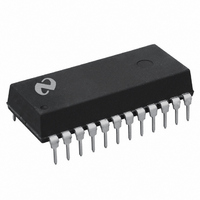
Manufacturer Part Number
DP8572AN
Description
IC REAL TIME CLOCK W/RAM 24 DIP
Manufacturer
National Semiconductor
Type
Clock/Calendar/NVSRAMr
Datasheet
1.DP8572AN.pdf
(22 pages)
Specifications of DP8572AN
Memory Size
44B
Time Format
HH:MM:SS:hh (12/24 hr)
Date Format
YY-MM-DD-dd
Interface
Parallel
Voltage - Supply
4.5 V ~ 5.5 V
Operating Temperature
-40°C ~ 85°C
Mounting Type
Through Hole
Package / Case
24-DIP (0.300", 7.62mm)
Lead Free Status / RoHS Status
Contains lead / RoHS non-compliant
Other names
*DP8572AN
DP8572
DP8572
Available stocks
Company
Part Number
Manufacturer
Quantity
Price

Part Number:
DP8572AN
Manufacturer:
TOSHIBA/东芝
Quantity:
20 000


Application Hints
Suggested Initialization Procedure for DP8572A in Battery
Backed Applications that use the V
1
2
3
4
Typical Application
Enter the test mode by writing a 1 to bit D7 in the Period-
ic Flag Register
Write zero to the RAM TEST mode Register located in
page 0 address HEX 1F
Leave the test mode by writing a 0 to bit D7 in the Peri-
odic Flag Register Steps 1 2 3 guarantee that if the test
mode had been entered during power on (due to ran-
dom pulses from the system) all test mode conditions
are cleared Most important is that the OSC Fail Disable
bit is cleared Refer to AN-589 for more information on
test mode operation
After power on (V
rect crystal frequency bits (D7 D6 in the Real Time
Mode Register) as shown in Table IV
5
5 1 Write a 1 to bit D3 in the Real Time Mode Register (try
Enter a software loop that does the following
Set a 3 second(approx) software counter The crystal
oscillator may take 1 second to start
to start the clock) Make sure the crystal select bits re-
main the same as in step 1 Under normal operation this
bit can be set only if the oscillator is running During the
32 768 KHz
4 194304 MHz
4 9152 MHz
32 0 KHz
Frequency
These components may be necessary to meet UL requirements for lithium batteries Consult battery manufacturer
CC
TABLE IV
and V
BB
powered) select the cor-
BB
D7
0
0
1
1
Pin
D6
0
1
0
1
19
6
7
8
9
10 Initialize the rest of the chip as needed
software loop RAM real time counters output configu-
ration interrupt control and timer functions may be ini-
tialized
Test bit D6 in the Periodic Flag Register
IF a 1 go to 5 1 If this bit remains a 1 after 3 seconds
then abort and check hardware The crystal may be
defective or not installed There may be a short at OSC
IN or OSC OUT to V
that is less than 10 M
IF a 0 then the oscillator is running go to step 7
Write a 0 to bit D6 in the Periodic Flag Register This
action puts the clock chip in the battery backed mode
This mode can be entered only if the OSC fail flag (bit
D6 of the Periodic Flag Register) is a 0 Reminder Bit
D6 is a dual function bit When read D6 returns oscilla-
tor status When written D6 causes either the Battery
Backed Mode or the Single Supply Mode of operation
The only method to ensure the chip is in the battery
backed mode is to measure the waveform at the OSC
OUT pin If the battery backed mode was selected suc-
cessfully then the peak to peak waveform at OSC OUT
is referenced to the battery voltage If not in battery
backed mode the waveform is referenced to V
measurement should be made with a high impedance
low capacitance probe (10 M
probe or better) Typical peak to peak swings are within
0 6V of V
Write a 1 to bit D7 of Interrupt Control Register 1 This
action enables the PFAIL pin and associated circuitry
Write a 1 to bit D4 of the Real Time Mode Register This
action ensures that bit D7 of Interrupt Control Register
1 remains a 1 when V
CC
and ground respectively
CC
BB l
or GND or to some impedance
V
CC
(Standby Mode)
10 pF oscilloscope
TL F 9980 – 19
CC
The
Related parts for DP8572AN
Image
Part Number
Description
Manufacturer
Datasheet
Request
R

Part Number:
Description:
National Semiconductor [8-Bit D/A Converter]
Manufacturer:
National Semiconductor
Datasheet:
Part Number:
Description:
National Semiconductor [Media Coprocessor]
Manufacturer:
National Semiconductor
Datasheet:
Part Number:
Description:
Digitally Controlled Tone and Volume Circuit with Stereo Audio Power Amplifier, Microphone Preamp Stage and National 3D Sound
Manufacturer:
National Semiconductor
Datasheet:
Part Number:
Description:
Digitally Controlled Tone and Volume Circuit with Stereo Audio Power Amplifier, Microphone Preamp Stage and National 3D Sound
Manufacturer:
National Semiconductor
Datasheet:
Part Number:
Description:
AC97 Rev 2 Codec with Sample Rate Conversion and National 3D Sound
Manufacturer:
National Semiconductor
Part Number:
Description:
Manufacturer:
National Semiconductor
Datasheet:
Part Number:
Description:
Manufacturer:
National Semiconductor
Datasheet:
Part Number:
Description:
General Purpose, Low Voltage, Low Power, Rail-to-Rail Output Operational Amplifiers
Manufacturer:
National Semiconductor
Datasheet:
Part Number:
Description:
8-bit 20 MSPS flash A/D converter.
Manufacturer:
National Semiconductor
Datasheet:
Part Number:
Description:
Low Noise Quad Operational Amplifier
Manufacturer:
National Semiconductor
Datasheet:
Part Number:
Description:
Quad Differential Line Receivers
Manufacturer:
National Semiconductor
Datasheet:
Part Number:
Description:
Quad High Speed Trapezoidal? Bus Transceiver
Manufacturer:
National Semiconductor
Datasheet:
Part Number:
Description:
Dual Line Receiver
Manufacturer:
National Semiconductor
Datasheet:
Part Number:
Description:
TTL to 10k ECL Level Translator with Latch
Manufacturer:
National Semiconductor
Datasheet: