MCP4728-E/UN Microchip Technology, MCP4728-E/UN Datasheet - Page 29
MCP4728-E/UN
Manufacturer Part Number
MCP4728-E/UN
Description
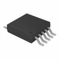
IC DAC 12BIT W/I2C 10-MSOP
Manufacturer
Microchip Technology
Specifications of MCP4728-E/UN
Number Of Converters
4
Settling Time
6µs
Package / Case
10-MSOP, Micro10™, 10-uMAX, 10-uSOP
Number Of Bits
12
Data Interface
I²C
Voltage Supply Source
Single Supply
Operating Temperature
-40°C ~ 125°C
Mounting Type
Surface Mount
Number Of Dac Outputs
4
Resolution
12 bit
Interface Type
I2C
Supply Voltage (max)
5.5 V
Supply Voltage (min)
2.7 V
Maximum Operating Temperature
+ 125 C
Mounting Style
SMD/SMT
Minimum Operating Temperature
- 40 C
Supply Current
110 mA
Voltage Reference
2.048 V
Lead Free Status / RoHS Status
Lead free / RoHS Compliant
For Use With
MCP4728EV - BOARD EVAL 12BIT 4CH DAC MCP4728
Power Dissipation (max)
-
Lead Free Status / Rohs Status
Lead free / RoHS Compliant
Available stocks
Company
Part Number
Manufacturer
Quantity
Price

Part Number:
MCP4728-E/UN
Manufacturer:
MICROCHIP/微芯
Quantity:
20 000


5.0
The MCP4728 device uses a two-wire I
interface. When the device is connected to the I
line, the device works as a slave device. The device
supports standard, fast and high speed modes.
The following sections describe how to communicate
with the MCP4728 device using the I
commands.
5.1
An example of the hardware connection diagram is
shown in
bus is defined as the transmitter, and a device receiving
data, as the receiver. The bus has to be controlled by a
master (MCU) device which generates the serial clock
(SCL), controls the bus access and generates the
START and STOP conditions. Both master (MCU) and
slave (MCP4728) can operate as transmitter or
receiver, but the master device determines which mode
is activated.
Communication is initiated by the master (MCU) which
sends the START bit, followed by the slave (MCP4728)
address byte. The first byte transmitted is always the
slave (MCP4728) address byte, which contains the
device code (1100), the address bits (A2, A1, A0), and
the R/W bit. The device code for the MCP4728 device
is 1100, and the address bits are user-writable.
When the MCP4728 device receives a Read command
(R/W = 1), it transmits the contents of the DAC input
registers and EEPROM sequentially. When writing to
the device (R/W = 0), the device will expect Write
command type bits in the following byte. The reading
and various writing commands are explained in the
following sections.
The MCP4728 device supports all three I
communication operating modes:
• Standard Mode: bit rates up to 100 kbit/s
• Fast Mode: bit rates up to 400 kbit/s
• High Speed Mode (HS mode): bit rates up to
Refer to the Philips I
the I
© 2010 Microchip Technology Inc.
3.4 Mbit/s
2
C specifications.
I
COMMUNICATIONS
Overview of I
Communications
Figure
2
C SERIAL INTERFACE
7-1. A device that sends data onto the
2
C document for more details of
2
C Serial Interface
2
C serial interface
2
2
C serial
C serial
2
C bus
5.1.1
The I
device must be ‘activated’ to operate in High-Speed
(3.4 Mbit/s) mode. This is done by sending a special
address byte of 00001XXX following the START bit.
The XXX bits are unique to the high-speed mode
Master. This byte is referred to as the high-speed
Master Mode Code (HSMMC). The MCP4728 device
does not acknowledge this byte. However, upon
receiving this command, the device switches to HS
mode and can communicate at up to 3.4 Mbit/s on SDA
and SCL lines. The device will switch out of the HS
mode on the next STOP condition.
For more information on the HS mode, or other I
modes, please refer to the Philips I
5.2
The specification of the I
defines the following bus protocol:
• Data transfer may be initiated only when the bus
• During data transfer, the data line must remain
Accordingly, the following bus conditions have been
defined using
5.2.1
Both data and clock lines remain HIGH.
5.2.2
A HIGH to LOW transition of the SDA line, while the
clock (SCL) is HIGH, determines a START condition.
All commands must be preceded by a START
condition.
5.2.3
A LOW to HIGH transition of the SDA line, while the
clock (SCL) is HIGH, determines a STOP condition. All
operations must be ended with a STOP condition.
5.2.4
The state of the data line represents valid data when,
after a START condition, the data line is stable for the
duration of the HIGH period of the clock signal.
The data on the line must be changed during the LOW
period of the clock signal. There is one clock pulse per
bit of data.
Each data transfer is initiated with a START condition
and terminated with a STOP condition.
is not busy
stable whenever the clock line is HIGH. Changes
in the data line while the clock line is HIGH will be
interpreted as a START or STOP condition
2
C specification requires that a high-speed mode
I
2
C BUS CHARACTERISTICS
HIGH-SPEED (HS) MODE
BUS NOT BUSY (A)
START DATA TRANSFER (B)
STOP DATA TRANSFER (C)
DATA VALID (D)
Figure
5-1.
2
C serial communication
MCP4728
2
C specification.
DS22187E-page 29
2
C
Related parts for MCP4728-E/UN
Image
Part Number
Description
Manufacturer
Datasheet
Request
R

Part Number:
Description:
12-bit, Quad Digital-to-analog Converter With Eeprom Memory
Manufacturer:
Microchip Technology Inc.
Datasheet:
Part Number:
Description:
Manufacturer:
Microchip Technology Inc.
Datasheet:
Part Number:
Description:
Manufacturer:
Microchip Technology Inc.
Datasheet:
Part Number:
Description:
Manufacturer:
Microchip Technology Inc.
Datasheet:
Part Number:
Description:
Manufacturer:
Microchip Technology Inc.
Datasheet:
Part Number:
Description:
Manufacturer:
Microchip Technology Inc.
Datasheet:
Part Number:
Description:
Manufacturer:
Microchip Technology Inc.
Datasheet:
Part Number:
Description:
Manufacturer:
Microchip Technology Inc.
Datasheet:
Part Number:
Description:
Manufacturer:
Microchip Technology Inc.
Datasheet: