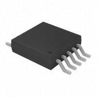
MCP4728-E/UN Microchip Technology, MCP4728-E/UN Datasheet - Page 53

MCP4728-E/UN
Manufacturer Part Number
MCP4728-E/UN
Description
IC DAC 12BIT W/I2C 10-MSOP
Manufacturer
Microchip Technology
Specifications of MCP4728-E/UN
Number Of Converters
4
Settling Time
6µs
Package / Case
10-MSOP, Micro10™, 10-uMAX, 10-uSOP
Number Of Bits
12
Data Interface
I²C
Voltage Supply Source
Single Supply
Operating Temperature
-40°C ~ 125°C
Mounting Type
Surface Mount
Number Of Dac Outputs
4
Resolution
12 bit
Interface Type
I2C
Supply Voltage (max)
5.5 V
Supply Voltage (min)
2.7 V
Maximum Operating Temperature
+ 125 C
Mounting Style
SMD/SMT
Minimum Operating Temperature
- 40 C
Supply Current
110 mA
Voltage Reference
2.048 V
Lead Free Status / RoHS Status
Lead free / RoHS Compliant
For Use With
MCP4728EV - BOARD EVAL 12BIT 4CH DAC MCP4728
Power Dissipation (max)
-
Lead Free Status / Rohs Status
Lead free / RoHS Compliant
Available stocks
Company
Part Number
Manufacturer
Quantity
Price
Part Number:
MCP4728-E/UN
Manufacturer:
MICROCHIP/微芯
Quantity:
20 000
7.6
The MCP4728 device is a rail-to-rail output DAC
designed to operate with a V
Its output amplifier of each channel is robust enough to
drive common, small-signal loads directly, thus
eliminating the cost and size of external buffers for
most applications. Since each channel has its own
configuration bits for selecting the voltage reference,
gain, power-down, etc., the MCP4728 device offers
great simplicity and flexibility to use for various DAC
applications.
© 2010 Microchip Technology Inc.
Application Examples
DD
range of 2.7V to 5.5V.
7.6.1
A common application for the MCP4728 device is a
digitally-controlled set point or a calibration of variable
parameters such as sensor offset or bias point.
Figure 7-3
Let us consider that the application requires different
trip voltages (Trip 1 - Trip 4). Assuming the DAC output
voltage requirements are given as shown in
examples of sending the Sequential Write and Fast
Write commands are shown in
Figure
TABLE 7-1:
DAC Channel
V
V
V
V
OUT
OUT
OUT
OUT
7-5.
shows an example of the set point settings.
A
B
C
D
DC SET POINT OR CALIBRATION
VOLTAGE SETTINGS
EXAMPLE: SETTING V
EACH CHANNEL
Reference
Voltage
Internal
Internal
V
V
DD
DD
MCP4728
DS22187E-page 53
Figure 7-4
DAC Output
V
DD
2.048V
4.096V
(V
V
DD
- 1 LSB
Table
OUT
OUT
/2
)
OF
7-1,
and


