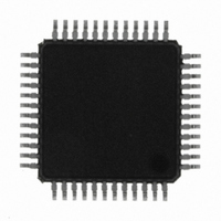
CS4384-CQZ Cirrus Logic Inc, CS4384-CQZ Datasheet - Page 6

CS4384-CQZ
Manufacturer Part Number
CS4384-CQZ
Description
IC DAC 8CH 103DB 192KHZ 48LQFP
Manufacturer
Cirrus Logic Inc
Datasheet
1.CS4384-CQZ.pdf
(52 pages)
Specifications of CS4384-CQZ
Data Interface
Serial
Number Of Bits
24
Number Of Converters
8
Voltage Supply Source
Analog and Digital
Power Dissipation (max)
520mW
Operating Temperature
-40°C ~ 85°C
Mounting Type
Surface Mount
Package / Case
48-LQFP
Resolution (bits)
24bit
Sampling Rate
192kSPS
Input Channel Type
Serial
Supply Voltage Range - Analog
4.75V To 5.25V
Supply Current
83mA
Digital Ic Case Style
QFP
Lead Free Status / RoHS Status
Lead free / RoHS Compliant
For Use With
598-1525 - BOARD EVAL FOR CS4384 DAC
Settling Time
-
Lead Free Status / RoHS Status
Lead free / RoHS Compliant, Lead free / RoHS Compliant
Other names
598-1062
Available stocks
Company
Part Number
Manufacturer
Quantity
Price
Company:
Part Number:
CS4384-CQZR
Manufacturer:
Cirrus Logic Inc
Quantity:
10 000
6
1. PIN DESCRIPTION
VD
GND
MCLK
LRCK
SDIN1
SDIN2
SDIN3
SDIN4
SCLK
VLC
RST
FILT+
VQ
MUTEC1
MUTEC234
Pin Name
31
13
14
18
19
20
21
41
22
11
#
4
5
6
7
8
9
Digital Power (Input) - Positive power supply for the digital section. Refer to the Recommended
Operating Conditions for appropriate voltages.
Ground (Input) - Ground reference. Should be connected to analog ground.
Master Clock (Input) - Clock source for the delta-sigma modulator and digital filters.
trates several standard audio sample rates and the required master clock frequencies.
Left Right Clock (Input) - Determines which channel, Left or Right, is currently active on the serial
audio data line. The frequency of the left/right clock must be at the audio sample rate, Fs.
Serial Data Input (Input) - Input for two’s complement serial audio data.
Serial Clock (Input) - Serial clocks for the serial audio interface.
Control Port Power (Input) - Determines the required signal level for the control port and hard-
ware mode configuration pins. Refer to the Recommended Operating Conditions for appropriate
voltages.
Reset (Input) - The device enters a low power mode and all internal registers are reset to their
default settings when low.
Positive Voltage Reference (Output) - Positive reference voltage for the internal sampling cir-
cuits. Requires the capacitive decoupling to analog ground as shown in the Typical Connection
Diagram.
Quiescent Voltage (Output) - Filter connection for internal quiescent voltage.
Mute Control (Output) - These pins are intended to be used as a control for external mute circuits
on the line outputs to prevent the clicks and pops that can occur in any single supply system.
M4(TST)
M3(TST)
DSD3
SDIN2
DSD2
DSD1
SDIN1
MCLK
SCLK
LRCK
GND
VD
1
2
3
4
5
7
8
9
10
11
6
12
48 47 46 45 44 43 42 41 40 39 38 37
13 14 15 16 17 18 19 20 21 22 23 24
CS4384
Pin Description
36
26
35
34
33
32
31
30
29
28
27
25
AOUT7
TST_OUT
AOUT3
AOUT4
TST_OUT
VA
GND
TST_OUT
AOUT5
AOUT6
TST_OUT
TST_OUT
Table 1
CS4384
DS620F1
illus-


