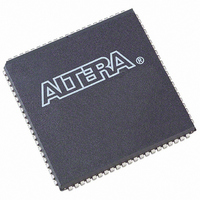
EPM9320LC84-15 Altera, EPM9320LC84-15 Datasheet - Page 40

EPM9320LC84-15
Manufacturer Part Number
EPM9320LC84-15
Description
IC MAX 9000 CPLD 320 84-PLCC
Manufacturer
Altera
Series
MAX® 9000r
Datasheet
1.EPM9320LC84-15.pdf
(46 pages)
Specifications of EPM9320LC84-15
Programmable Type
In System Programmable
Delay Time Tpd(1) Max
15.0ns
Voltage Supply - Internal
4.75 V ~ 5.25 V
Number Of Logic Elements/blocks
20
Number Of Macrocells
320
Number Of Gates
6000
Number Of I /o
60
Operating Temperature
0°C ~ 70°C
Mounting Type
Surface Mount
Package / Case
84-PLCC
Voltage
3.3V/5V
Memory Type
EEPROM
Number Of Logic Elements/cells
20
Lead Free Status / RoHS Status
Contains lead / RoHS non-compliant
Features
-
Other names
544-2362-5
Available stocks
Company
Part Number
Manufacturer
Quantity
Price
Company:
Part Number:
EPM9320LC84-15
Manufacturer:
ALTERA
Quantity:
1 560
Company:
Part Number:
EPM9320LC84-15
Manufacturer:
ALTERA20
Quantity:
51
Company:
Part Number:
EPM9320LC84-15N
Manufacturer:
ALTERA
Quantity:
4
MAX 9000 Programmable Logic Device Family Data Sheet
Notes:
(1)
(2)
(3)
(4)
(5)
Notes:
(1)
(2)
(3)
(4)
40
DIN1 (GCLK1)
DIN2 (GCLK2)
DIN3 (GCLR)
DIN4 (GOE)
TCK
TMS
TDI
TDO
GND
VCCINT (5.0 V only)
VCCIO (3.3 or 5.0 V)
No Connect (N.C.)
VPP
Total User I/O Pins
Table 27. EPM9400 Dedicated Pin-Outs
All pins not listed are user I/O pins.
Perform a complete thermal analysis before committing a design to this device package. See
(Evaluating Power for Altera
EPM9320A devices are not offered in this package.
During in-system programming, each device’s VPP pin must be connected to the 5.0-V power supply. During
normal device operation, the VPP pin is pulled up internally and can be connected to the 5.0-V supply or left
unconnected.
The user I/O pin count includes dedicated input pins and all I/O pins.
All pins not listed are user I/O pins.
Perform a complete thermal analysis before committing a design to this device package. See
(Evaluating Power for Altera Devices)
During in-system programming, each device’s
normal device operation, the
unconnected.
The user I/O pin count includes dedicated input pins and all I/O pins.
(3)
Pin Name
(4)
2
1
12
74
43
54
42
31
6, 13, 20, 26, 27, 47, 60,
66, 69, 73
16, 23, 30, 56, 63, 70
17, 37, 59, 80
–
55
59
Devices).
VPP
84-Pin PLCC
pin is pulled up internally and can be connected to the 5.0-V supply or left
for more information.
Note (1)
(2)
VPP
pin must be connected to the 5.0-V power supply. During
182
183
153
4
78
49
79
108
14, 20, 24, 31, 35, 41, 42,
43, 44, 46, 47, 66, 85, 102,
110, 113, 114, 115, 116,
118, 121, 122, 132, 133,
143, 152, 170, 189, 206
10, 19, 30, 45, 112, 128,
139, 148
5, 25, 36, 55, 72, 91, 111,
127, 138, 159, 176, 195
6, 7, 8, 9, 11, 12, 13, 109,
144, 145, 146, 147, 149,
150, 151
48
139
208-Pin RQFP
210
211
187
234
91
68
92
114
5, 14, 25, 34, 45, 54, 65,
66, 81, 96, 110, 115, 126,
127, 146, 147, 166, 167,
186, 200, 216, 229
4, 24, 44, 64, 117, 137,
157, 177
15, 35, 55, 73, 86, 101,
116, 136, 156, 176, 192,
205, 220, 235
1, 2, 3, 6, 7, 8, 9, 10, 11,
12, 13, 168, 169, 170,
171, 172, 173, 174, 175,
178, 179, 180, 181, 182,
183, 184, 185, 236, 237,
238, 239, 240
67
159
240-Pin RQFP
Application Note 74
Application Note 74
Altera Corporation


