DSP56303AG100 Freescale Semiconductor, DSP56303AG100 Datasheet - Page 21
DSP56303AG100
Manufacturer Part Number
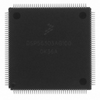
DSP56303AG100
Description
IC DSP 24BIT 100MHZ 144-LQFP
Manufacturer
Freescale Semiconductor
Series
DSP563xxr
Type
Fixed Pointr
Datasheet
1.DSP56303AG100.pdf
(108 pages)
Specifications of DSP56303AG100
Interface
Host Interface, SSI, SCI
Clock Rate
100MHz
Non-volatile Memory
ROM (576 B)
On-chip Ram
24kB
Voltage - I/o
3.30V
Voltage - Core
3.30V
Operating Temperature
-40°C ~ 100°C
Mounting Type
Surface Mount
Package / Case
144-LQFP
Package
144LQFP
Maximum Speed
100 MHz
Ram Size
24 KB
Device Million Instructions Per Second
100 MIPS
Lead Free Status / RoHS Status
Lead free / RoHS Compliant
Available stocks
Company
Part Number
Manufacturer
Quantity
Price
Company:

Part Number:
DSP56303AG100
Manufacturer:
Freescale Semiconductor
Quantity:
10 000
Company:
Part Number:
DSP56303AG100B1
Manufacturer:
Freescale Semiconductor
Quantity:
10 000
Company:
Part Number:
DSP56303AG100R2
Manufacturer:
Freescale Semiconductor
Quantity:
10 000


Specifications
The
2.1 Maximum Ratings
In the calculation of timing requirements, adding a maximum value of one specification to a minimum value of
another specification does not yield a reasonable sum. A maximum specification is calculated using a worst case
variation of process parameter values in one direction. The minimum specification is calculated using the worst
case for the same parameters in the opposite direction. Therefore, a “maximum” value for a specification never
occurs in the same device that has a “minimum” value for another specification; adding a maximum to a minimum
represents a condition that can never exist.
2.2 Absolute Maximum Ratings
Freescale Semiconductor
Supply Voltage
All input voltages excluding “5 V tolerant” inputs
All “5 V tolerant” input voltages
Current drain per pin excluding V
Operating temperature range
Storage temperature
Notes:
DSP56303
1.
2.
Absolute maximum ratings are stress ratings only, and functional operation at the maximum is not guaranteed. Stress beyond
the maximum rating may affect device reliability or cause permanent damage to the device.
At power-up, ensure that the voltage difference between the 5 V tolerant pins and the chip V
is fabricated in high-density CMOS with transistor-transistor logic (TTL) compatible inputs and outputs.
Rating
2
CC
and GND
This device contains circuitry protecting
against damage due to high static voltage or
electrical fields; however, normal precautions
should be taken to avoid exceeding maximum
voltage ratings. Reliability is enhanced if
unused inputs are tied to an appropriate logic
voltage level (for example, either GND or V
Table 2-1.
DSP56303 Technical Data, Rev. 11
Absolute Maximum Ratings
CAUTION
Symbol
T
V
V
V
T
STG
CC
IN5
I
IN
J
GND
GND
1
−
−
−
−
0.3 to +4.0
40 to +100
55 to +150
CC
0.3 to V
Value
−
0.3 to 5.5
10
).
CC
CC
+ 0.3
never exceeds 3.5 V.
Unit
mA
°
°
V
V
V
C
C
2
2-1
Related parts for DSP56303AG100
Image
Part Number
Description
Manufacturer
Datasheet
Request
R

Part Number:
Description:
DSP56303 USER�S MANUAL
Manufacturer:
FREESCALE [Freescale Semiconductor, Inc]
Datasheet:
Part Number:
Description:
DSP56303 Software Differences Between the DSP56002 and the DSP56303
Manufacturer:
Freescale Semiconductor / Motorola
Part Number:
Description:
DSP56303 Hardware Differences Between the DSP56002 and the DSP56303
Manufacturer:
Freescale Semiconductor / Motorola

Part Number:
Description:
Manufacturer:
Freescale Semiconductor, Inc
Datasheet:
Part Number:
Description:
Manufacturer:
Freescale Semiconductor, Inc
Datasheet:
Part Number:
Description:
Manufacturer:
Freescale Semiconductor, Inc
Datasheet:
Part Number:
Description:
Manufacturer:
Freescale Semiconductor, Inc
Datasheet:
Part Number:
Description:
Manufacturer:
Freescale Semiconductor, Inc
Datasheet:
Part Number:
Description:
Manufacturer:
Freescale Semiconductor, Inc
Datasheet:
Part Number:
Description:
Manufacturer:
Freescale Semiconductor, Inc
Datasheet:
Part Number:
Description:
Manufacturer:
Freescale Semiconductor, Inc
Datasheet:
Part Number:
Description:
Manufacturer:
Freescale Semiconductor, Inc
Datasheet:
Part Number:
Description:
Manufacturer:
Freescale Semiconductor, Inc
Datasheet:
Part Number:
Description:
Manufacturer:
Freescale Semiconductor, Inc
Datasheet:
Part Number:
Description:
Manufacturer:
Freescale Semiconductor, Inc
Datasheet: