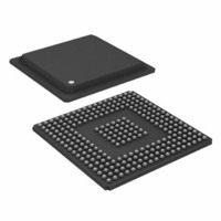
ADSP-BF535PKB-350 Analog Devices Inc, ADSP-BF535PKB-350 Datasheet - Page 24

ADSP-BF535PKB-350
Manufacturer Part Number
ADSP-BF535PKB-350
Description
IC DSP CONTROLLER 16BIT 260 BGA
Manufacturer
Analog Devices Inc
Series
Blackfin®r
Type
Fixed Pointr
Specifications of ADSP-BF535PKB-350
Rohs Status
RoHS non-compliant
Interface
PCI, SPI, SSP, UART, USB
Clock Rate
350MHz
Non-volatile Memory
External
On-chip Ram
308kB
Voltage - I/o
3.30V
Voltage - Core
1.60V
Operating Temperature
0°C ~ 70°C
Mounting Type
Surface Mount
Package / Case
260-BGA
Device Core Size
32b
Architecture
Modified Harvard
Format
Floating Point
Clock Freq (max)
350MHz
Device Input Clock Speed
350MHz
Program Memory Size
Not RequiredKB
Operating Temp Range
0C to 70C
Operating Temperature Classification
Commercial
Mounting
Surface Mount
Package Type
BGA
Lead Free Status / Rohs Status
Not Compliant
Available stocks
Company
Part Number
Manufacturer
Quantity
Price
Company:
Part Number:
ADSP-BF535PKB-350
Manufacturer:
Analog Devices Inc
Quantity:
10 000
Company:
Part Number:
ADSP-BF535PKB-350 1.3
Manufacturer:
ADI
Quantity:
246
ADSP-BF535
Clock and Reset Timing
Table 11
ABSOLUTE MAXIMUM RATINGS on Page
tions of CLKIN and clock multipliers must not select core and
system clocks in excess of 350/300/200 MHz and 133 MHz,
respectively.
Table 11. Clock and Reset Timing
1
2
3
4
Parameter
Timing Requirements
t
t
t
t
t
t
t
Switching Characteristics
t
Applies to Bypass mode and Non-bypass mode.
Applies after power-up sequence is complete. At power-up, the processor’s internal phase-locked loop requires no more than 2000 CLKIN cycles, while
SSELx, MSELx and DF values can change from this point, but the values must be valid.
SSELx, MSELx and DF values must be held from this time, until the hold time expires.
CKIN
CKINL
CKINH
WRST
MSD
MSS
MSH
PFD
RESET is asserted, assuming stable power supplies and CLKIN (not including start-up time of external clock oscillator).
and
SSEL1–0
MSEL6–0
BYPASS
RESET
Figure 8
CLKIN
DF
CLKIN Period
CLKIN Low Pulse
CLKIN High Pulse
RESET Asserted Pulse Width Low
Delay from RESET Asserted to MSELx, SSELx, BYPASS,
and DF Valid
MSELx/SSELx/DF/BYPASS Stable Setup Before RESET
Deasserted
MSELx/SSELx/DF/BYPASS Stable Hold After RESET
Deasserted
Flag Output Disable Time After RESET Asserted
describe clock and reset operations. Per
t
C K IN L
4
3
t
C K IN
t
1
C K IN H
1
t
P F D
t
M S D
Figure 8. Clock and Reset Timing
22, combina-
t
W R S T
2
t
M S S
–24–
t
M S H
Min
25.0
10.0
10.0
11 t
2 t
2 t
CKIN
CKIN
CKIN
Max
100.0
15.0
15.0
REV. A
Unit
ns
ns
ns
ns
ns
ns
ns
ns


