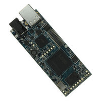
DLP-HS-FPGA DLP Design Inc, DLP-HS-FPGA Datasheet - Page 6

DLP-HS-FPGA
Manufacturer Part Number
DLP-HS-FPGA
Description
MODULE USB-TO-FPGA SPARTAN3
Manufacturer
DLP Design Inc
Datasheet
1.DLP-HS-FPGA.pdf
(17 pages)
Specifications of DLP-HS-FPGA
Module/board Type
FPGA Module
Interface Type
USB, SPI
Data Bus Width
32 bit
Operating Supply Voltage
5 V
Product
Interface Modules
For Use With/related Products
USB
Lead Free Status / RoHS Status
Lead free / RoHS Compliant
Lead Free Status / RoHS Status
Lead free / RoHS Compliant, Lead free / RoHS Compliant
Other names
813-1030
Available stocks
Company
Part Number
Manufacturer
Quantity
Price
Company:
Part Number:
DLP-HS-FPGA
Manufacturer:
DLP Design
Quantity:
135
7.0 EEPROM SETUP / MPROG
The DLP-HS-FPGA has a dual-channel USB interface to the host PC. Channel A is used exclusively
to load an FPGA configuration (.bit) file to the SPI flash. This configuration data is automatically
transferred to the FPGA when power is applied to the module, or when the PROG pin is driven low
and then released, by the application software. Channel B is used for communication between the
FPGA and host PC at run time. A 93LC56B EEPROM connected to the USB interface IC is used to
store the setup for the two channels. The parameters stored in the EEPROM include the Vendor ID
(VID), Product ID (PID), Serial Number, Description String, driver selection (VCP or D2XX) and port
type (UART serial or FIFO parallel).
As mentioned above, Channel A is used exclusively for loading the FPGA’s configuration to the SPI
flash, and Channel B is used for communication between the host PC and the DLP-HS-FPGA. As
such, the D2XX drivers and 245 FIFO mode must be selected in the EEPROM for Channel A.
Channel B must use the 245 FIFO mode, but can use either the VCP or D2XX drivers. The VCP
drivers make the DLP-HS-FPGA appear as an RS232 port to the host application. The D2XX drivers
provide faster throughput, but require working with a .lib or .dll library in the host application.
The operational modes and other EEPROM selections are written to the EEPROM using the MPROG
utility. This utility and its manual are available for download from the bottom of the page at
www.dlpdesign.com.
8.0 TEST BIT FILE
A test file is provided as a download from the DLP Design website that provides rudimentary access
to the I/O features of the DLP-HS-FPGA.
The following features are provided:
This bit file is available from the DLP-HS-FPGA’s download page. The command structure that
supports these features is explained in section 10.
Rev. 1.1 (December 2009)
•
•
•
•
•
Ping
Read the High/Low State of the Input-Only Pins
Drive I/O Pins High/Low or Read their High/Low State
Simple Loopback on Channel B
Simple Read/Write of Each Address in the DDR2 SDRAM
6
© DLP Design, Inc.


