GC80503CSM66166SL388 Intel, GC80503CSM66166SL388 Datasheet - Page 23
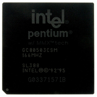
GC80503CSM66166SL388
Manufacturer Part Number
GC80503CSM66166SL388
Description
IC MPU 1.9V PENTI 166MHZ 352BGA
Manufacturer
Intel
Datasheet
1.GC80503CSM66166SL388.pdf
(62 pages)
Specifications of GC80503CSM66166SL388
Rohs Status
RoHS non-compliant
Processor Type
Pentium I w/MMX
Features
66MHz Bus
Speed
166MHz
Voltage
1.9V
Mounting Type
Surface Mount
Package / Case
352-BGA
Other names
821225


3.4
3.5
Datasheet
Table 6. Quick Pin Reference (Sheet 1 of 6)
Note: All input pins must meet their AC/DC specifications to guarantee proper functional behavior.
Design Notes
For reliable operation, always connect unused inputs to an appropriate signal level. Unused active
low inputs should be connected to V
(V
No Connect (NC) pins must remain unconnected. Connection of NC pins may result in component
failure or incompatibility with processor steppings.
Pin Quick Reference
This section gives a brief functional description of each pin. For a detailed description, see the
Hardware Interface chapter in the Embedded Pentium
The # symbol at the end of a signal name indicates that the active or asserted state occurs when the
signal is at a low voltage. When a # symbol is not present after the signal name, the signal is active,
or asserted at the high voltage level. Square brackets around a signal name indicate that the signal
is defined only at RESET.
The pins are classified as Input or Output based on their function in Master Mode. See the Error
Detection chapter of the Embedded Pentium
number 273204) for further information.
A20M#
A31–A3
ADS#
AHOLD
AP
APCHK#
BE7#
BE4#
SS
Symbol
).
–
–
BE5#
BE0#
Type
Low-Power Embedded Pentium
I/O
I/O
I/O
O
O
O
I
I
When the address bit 20 mask pin is asserted, the Pentium
MMX™ technology emulates the address wraparound at 1 Mbyte, which occurs on
the 8086. When A20M# is asserted, the processor masks physical address bit 20
(A20) before performing a lookup to the internal caches or driving a memory cycle
on the bus. The effect of A20M# is undefined in protected mode. A20M# must be
asserted only when the processor is in real mode.
As outputs, the address lines of the processor along with the byte enables define
the physical area of memory or I/O accessed. The external system drives the
inquire address to the processor on A31
The address status indicates that a new valid bus cycle is currently being driven by
the processor.
In response to the assertion of address hold, the processor will stop driving the
address lines (A31
active so data can be returned or driven for previously issued bus cycles.
Address parity is driven by the processor with even parity information on all
processor generated cycles in the same clock that the address is driven. Even
parity must be driven back to the processor during inquire cycles on this pin in the
same clock as EADS# to ensure that correct parity check status is indicated.
The address parity check status pin is asserted two clocks after EADS# is
sampled active if the processor has detected a parity error on the address bus
during inquire cycles. APCHK# will remain active for one clock each time a parity
error is detected.
The byte enable pins are used to determine which bytes must be written to external
memory, or which bytes were requested by the CPU for the current cycle. The byte
enables are driven in the same clock as the address lines (A31-3).
CC3
. Unused active high inputs should be connected to GND
–
A3) and AP in the next clock. The rest of the bus will remain
®
Processor Family Developer’s Manual (order
Name and Function
®
®
Processor Family Developer’s Manual.
Processor with MMX™ Technology
–
A5.
®
processor with
23
Related parts for GC80503CSM66166SL388
Image
Part Number
Description
Manufacturer
Datasheet
Request
R

Part Number:
Description:
Microprocessor: Intel Celeron M Processor 320 and Ultra Low Voltage Intel Celeron M Processor at 600MHz
Manufacturer:
Intel Corporation
Part Number:
Description:
Intel 82550 Fast Ethernet Multifunction PCI/CardBus Controller
Manufacturer:
Intel Corporation
Datasheet:
Part Number:
Description:
Intel StrataFlash memory 32 Mbit. Access speed 120 ns
Manufacturer:
Intel Corporation
Datasheet:
Part Number:
Description:
Intel StrataFlash memory 32 Mbit. Access speed 120 ns
Manufacturer:
Intel Corporation
Datasheet:
Part Number:
Description:
Intel StrataFlash memory 64 Mbit. Access speed 150 ns
Manufacturer:
Intel Corporation
Datasheet:
Part Number:
Description:
Intel StrataFlash memory 32 Mbit. Access speed 100 ns
Manufacturer:
Intel Corporation
Datasheet:
Part Number:
Description:
DA28F640J5A-1505 Volt Intel StrataFlash Memory
Manufacturer:
Intel Corporation
Datasheet:
Part Number:
Description:
5 Volt Intel StrataFlash?? Memory
Manufacturer:
Intel Corporation
Datasheet:
Part Number:
Description:
5 Volt Intel StrataFlash?? Memory
Manufacturer:
Intel Corporation
Part Number:
Description:
Intel 6300ESB I/O Controller Hub
Manufacturer:
Intel Corporation
Datasheet:
Part Number:
Description:
Intel 82801DB I/O Controller Hub (ICH4), Pb-Free SLI
Manufacturer:
Intel Corporation
Datasheet:
Part Number:
Description:
Intel 82801FB I/O Controller Hub (ICH6)
Manufacturer:
Intel Corporation
Datasheet:
Part Number:
Description:
Intel Strataflash Memory28F128J3 28F640J3 28F320J3
Manufacturer:
Intel Corporation
Datasheet:
Part Number:
Description:
Controllers, Intel 430TX PCIset: 82439TX System Controller (MTXC)
Manufacturer:
Intel Corporation