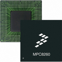
MPC8260AZUPIBB Freescale Semiconductor, MPC8260AZUPIBB Datasheet - Page 6

MPC8260AZUPIBB
Manufacturer Part Number
MPC8260AZUPIBB
Description
IC MPU POWERQUICC II 480-TBGA
Manufacturer
Freescale Semiconductor
Series
PowerQUICC IIr
Specifications of MPC8260AZUPIBB
Processor Type
MPC82xx PowerQUICC II 32-bit
Speed
300MHz
Voltage
2V
Mounting Type
Surface Mount
Package / Case
480-TBGA
Core Size
32 Bit
Program Memory Size
32KB
Cpu Speed
300MHz
Embedded Interface Type
I2C, MII, SPI, TDM, UTOPIA
Digital Ic Case Style
TBGA
No. Of Pins
480
Rohs Compliant
No
For Use With
MPC8260ADS-TCOM - BOARD DEV ADS POWERQUICC II
Lead Free Status / RoHS Status
Contains lead / RoHS non-compliant
Features
-
Available stocks
Company
Part Number
Manufacturer
Quantity
Price
Company:
Part Number:
MPC8260AZUPIBB
Manufacturer:
Freescale Semiconductor
Quantity:
10 000
Electrical and Thermal Characteristics
Table 2
This device contains circuitry protecting against damage due to high static voltage or electrical fields;
however, it is advised that normal precautions be taken to avoid application of any voltages higher than
maximum-rated voltages to this high-impedance circuit. Reliability of operation is enhanced if unused
inputs are tied to an appropriate logic voltage level (either GND or V
Figure 2
MPC8280. Note that in PCI mode the I/O interface is different.
6
1
2
Core supply voltage
PLL supply voltage
I/O supply voltage
Input voltage
Junction temperature (maximum)
Caution: These are the recommended and tested operating conditions. Proper device operating outside of these
conditions is not guaranteed.
Parts labeled with an “-HVA” suffix are 2.6-V devices.
lists recommended operational voltage conditions.
shows the undershoot and overshoot voltage of the 60x and local bus memory interface of the
MPC8260 PowerQUICC II Integrated Communications Processor Hardware Specifications, Rev. 2
VDDH, VCCSYN, and VDD must track each other and both must vary in
the same direction—in the positive direction (+5% and +0.1 Vdc) or in the
negative direction (–5% and –0.1 Vdc).
Rating
V
V
IH
IL
GND – 0.3 V
GND – 1.0 V
GV
Table 2. Recommended Operating Conditions
DD
NOTE: Core, PLL, and I/O Supply Voltages
GV
+ 5%
GND
Figure 2. Overshoot/Undershoot Voltage
4 V
DD
VCCSYN
Symbol
VDDH
VDD
VIN
T
j
Not to exceed 10%
of t
SDRAM_CLK
GND (-0.3) – 3.465
2.5-V Device
3.135 – 3.465
2.4–2.7
2.4–2.7
CC
105
).
1
2
Freescale Semiconductor
Unit
°C
V
V
V
V


