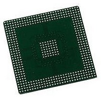
MPC5200CBV400 Freescale Semiconductor, MPC5200CBV400 Datasheet - Page 74

MPC5200CBV400
Manufacturer Part Number
MPC5200CBV400
Description
IC MPU 32BIT 400MHZ PPC 272-PBGA
Manufacturer
Freescale Semiconductor
Datasheet
1.MPC5200CVR400B.pdf
(80 pages)
Specifications of MPC5200CBV400
Processor Type
MPC52xx PowerPC 32-Bit
Speed
400MHz
Voltage
1.5V
Mounting Type
Surface Mount
Package / Case
272-PBGA
Core Size
32 Bit
No. Of I/o's
56
Ram Memory Size
16KB
Cpu Speed
400MHz
No. Of Timers
8
Embedded Interface Type
CAN, I2C, SPI, UART, USB
No. Of Pwm Channels
8
Digital Ic Case Style
BGA
Rohs Compliant
No
Family Name
MPC52xx
Device Core
PowerPC
Device Core Size
32b
Frequency (max)
400MHz
Instruction Set Architecture
RISC
Supply Voltage 1 (typ)
1.5V
Operating Supply Voltage (max)
1.58V
Operating Supply Voltage (min)
1.42V
Operating Temp Range
-40C to 85C
Operating Temperature Classification
Industrial
Mounting
Surface Mount
Pin Count
272
Package Type
BGA
Lead Free Status / RoHS Status
Contains lead / RoHS non-compliant
Features
-
Lead Free Status / Rohs Status
Not Compliant
Available stocks
Company
Part Number
Manufacturer
Quantity
Price
Company:
Part Number:
MPC5200CBV400
Manufacturer:
FREESCAL
Quantity:
200
Company:
Part Number:
MPC5200CBV400
Manufacturer:
Freescale Semiconductor
Quantity:
10 000
Company:
Part Number:
MPC5200CBV400B
Manufacturer:
FREESCAL
Quantity:
200
System Design Information
5.3.2
If the PCI interface is NOT used (and internally disabled) the PCI control pins must be terminated as
indicated by the PCI Local Bus specification [4]. This is also required for MOST/Graphics and Large Flash
Mode.
PCI control signals always require pull-up resistors on the motherboard (not the expansion board) to
ensure that they contain stable values when no agent is actively driving the bus. This includes
PCI_FRAME, PCI_TRDY, PCI_IRDY, PCI_DEVSEL, PCI_STOP, PCI_SERR, PCI_PERR, and
PCI_REQ.
5.3.3
The MEM_MDQS[3:0] signals are not used with SDR memories and require pull-up or pull-down
resistors in SDRAM mode.
5.4
The MPC5200 provides the user an IEEE 1149.1 JTAG interface to facilitate board/system testing. It also
provides a Common On-Chip Processor (COP) Interface, which shares the IEEE 1149.1 JTAG port. The
COP Interface provides access to the MPC5200's imbedded Freescale (formerly Motorola) MPC603e
G2_LE processor. This interface provides a means for executing test routines and for performing software
development & debug functions.
5.4.1
Boundary scan testing is enabled through the JTAG interface signals. The JTAG_TRST signal is optional
in the IEEE 1149.1 specification but is provided on all processors that implement the PowerPC
architecture. To obtain a reliable power-on reset performance, the JTAG_TRST signal must be asserted
during power-on reset.
5.4.1.1
The JTAG interface can control the direction of the MPC5200 I/O pads via the boundary scan chain. The
JTAG module must be reset before the MPC5200 comes out of power-on reset; do this by asserting
JTAG_TRST before PORRESET is released.
For more details refer to the Reset and JTAG Timing Specification.
74
JTAG
Pull-up Requirements for the PCI Control Lines
Pull-up/Pull-down Requirements for MEM_MDQS pins
(SDRAM)
JTAG_TRST
JTAG_TRST and PORRESET
MPC5200 Data Sheet, Rev. 4
Freescale Semiconductor


