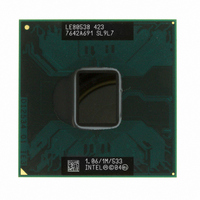
LE80538VE0041M Intel, LE80538VE0041M Datasheet - Page 66

LE80538VE0041M
Manufacturer Part Number
LE80538VE0041M
Description
IC PROC CELERON M 1.06GHZ 479BGA
Manufacturer
Intel
Datasheet
1.LE80535NC013512.pdf
(69 pages)
Specifications of LE80538VE0041M
Processor Type
Celeron M
Features
533MHZ Bus, 1M L2 Cache
Speed
1.06GHz
Voltage
0.94V
Mounting Type
Surface Mount
Package / Case
479-BGA
Lead Free Status / RoHS Status
Lead free / RoHS Compliant
Other names
883549
Available stocks
Company
Part Number
Manufacturer
Quantity
Price
Thermal Specifications and Design Considerations
5.1.2
66
Intel Thermal Monitor
The Intel Thermal Monitor helps control the processor temperature by activating the TCC when the
processor silicon reaches its maximum operating temperature. The temperature at which the Intel
Thermal Monitor activates the thermal control circuit (TCC) is not user configurable and is not
software visible. Bus traffic is snooped in the normal manner, and interrupt requests are latched
(and serviced during the time that the clocks are on) while the TCC is active.
With a properly designed and characterized thermal solution, it is anticipated that the TCC would
only be activated for very short periods of time when running the most power intensive
applications. The processor performance impact due to these brief periods of TCC activation is
expected to be so minor that it would not be detectable. An under-designed thermal solution that is
not able to prevent excessive activation of the TCC in the anticipated ambient environment may
cause a noticeable performance loss, and may affect the long-term reliability of the processor. In
addition, a thermal solution that is significantly underdesigned may not be capable of cooling the
processor even when the TCC is active continuously.
The Intel Thermal Monitor controls the processor temperature by modulating (starting and
stopping) the processor core clocks when the processor silicon reaches its maximum operating
temperature. The Intel Thermal Monitor uses two modes to activate the TCC: Automatic mode and
On-Demand mode. If both modes are activated, automatic mode takes precedence. The Intel
Thermal Monitor Automatic Mode must be enabled via BIOS for the processor to be operating
within specifications.This mode is selected by writing values to the Model Specific Registers
(MSRs) of the processor. After the automatic mode is enabled, the TCC will activate only when the
internal die temperature reaches the maximum allowed value for operation.
When Intel Thermal Monitor is enabled, and a high temperature situation exists, the clocks will be
modulated by alternately turning the clocks off and on at a 50% duty cycle. Cycle times are
processor speed dependent and will decrease linearly as processor core frequencies increase. After
the temperature has returned to a non-critical level, modulation ceases and the TCC goes inactive.
A small amount of hysteresis has been included to prevent rapid active/inactive transitions of the
TCC when the processor temperature is near the trip point. The duty cycle is factory configured
and cannot be modified. Also, the automatic mode does not require any additional hardware,
software drivers or interrupt handling routines. Processor performance will be decreased by the
same amount as the duty cycle when the TCC is active, however, with a properly designed and
characterized thermal solution the TCC most likely will never be activated, or will be activated
only briefly during the most power intensive applications.
The TCC may also be activated using On-Demand mode. If bit 4 of the ACPI Intel Thermal
Monitor Control register is written to a "1", the TCC will be activated immediately, independent of
the processor temperature. When using On-Demand mode to activate the TCC, the duty cycle of
the clock modulation is programmable via bits 3:1 of the same ACPI Intel Thermal Monitor
Control Register. In automatic mode, the duty cycle is fixed at 50% on, 50% off, in On-Demand
mode, the duty cycle can be programmed from 12.5% on/ 87.5% off, to 87.5% on/12.5% off in
5. The series resistance, R
I
Where I
and T = absolute temperature (Kelvin).
temperature. R
board trace resistance between the socket and the external remote diode thermal sensor. R
remote diode thermal sensors with automatic series resistance cancellation to calibrate out this error term.
Another application is that a temperature offset can be manually calculated and programmed into an offset
register in the remote diode thermal sensors as exemplified by the equation:
T
FW
error
=I
s
= [R
x
S
(e
= saturation current, q = electronic charge, V
T
(qV
x
D
(N-1)
/nkT)
T
as defined includes the pins of the processor but does not include any socket resistance or
-1)
x
I
FWmin
T
, is provided to allow for a more accurate measurement of the diode junction
]/[(no/q)
x
ln N]
D
= voltage across the diode, k = Boltzmann Constant,
Intel
®
Celeron
®
M Processor Datasheet
T
can be used by


