LM4550BVH/NOPB National Semiconductor, LM4550BVH/NOPB Datasheet - Page 21
LM4550BVH/NOPB
Manufacturer Part Number
LM4550BVH/NOPB
Description
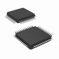
IC AC '97 AUDIO CODEC 48-LQFP
Manufacturer
National Semiconductor
Type
Audio Codec '97r
Specifications of LM4550BVH/NOPB
Data Interface
Serial
Resolution (bits)
18 b
Number Of Adcs / Dacs
2 / 2
Sigma Delta
Yes
Dynamic Range, Adcs / Dacs (db) Typ
90 / 89
Voltage - Supply, Analog
4.2 V ~ 5.5 V
Voltage - Supply, Digital
3 V ~ 5.5 V
Operating Temperature
-40°C ~ 85°C
Mounting Type
Surface Mount
Package / Case
48-LQFP
Audio Codec Type
Stereo
No. Of Adcs
2
No. Of Dacs
2
No. Of Input Channels
8
No. Of Output Channels
3
Adc / Dac Resolution
18bit
Sampling Rate
48kSPS
Interface Type
Serial
Supply Voltage Range
3V To 5.5V, 4.2V
Rohs Compliant
Yes
Lead Free Status / RoHS Status
Lead free / RoHS Compliant
Other names
*LM4550BVH
*LM4550BVH/NOPB
LM4550BVH
*LM4550BVH/NOPB
LM4550BVH
Available stocks
Company
Part Number
Manufacturer
Quantity
Price
Company:

Part Number:
LM4550BVH/NOPB
Manufacturer:
STM
Quantity:
1 872
Company:
Part Number:
LM4550BVH/NOPB
Manufacturer:
Texas Instruments
Quantity:
10 000


AC Link Serial Interface Protocol
A new Input Frame is signaled with a low-to-high transition of
SYNC. SYNC should be clocked from the controller on a
rising edge of BIT_CLK and, as shown in Figure 6 and
Figure 7, the first tag bit in the Frame (“Codec Ready”) is
clocked from the LM4550 by the next rising edge of BIT-
_CLK. The LM4550 always clocks data to SDATA_IN on a
rising edge of BIT_CLK and the controller is expected to
sample SDATA_IN on the next falling edge. The LM4550
samples SYNC on the rising edge of BIT_CLK.
Input and Output Frames are aligned to the same SYNC
transition.
The LM4550 checks each Frame to ensure 256 bits are
received. If a new Frame is detected (a low-to-high transition
on SYNC) before 256 bits are received from an old Frame
then the new Frame is ignored i.e. no valid data is sent on
SDATA_IN until a valid new Frame is detected.
The LM4550 transmits data MSB first, in an MSB justified
format. All reserved bits and slots are stuffed with "0"s by the
LM4550.
SDATA_IN: Slot 0 – Codec/Slot Status Bits
The first bit (bit 15, “Codec Ready”) of slot 0 in the AC Link
Input Frame indicates when the codec’s AC Link digital
interface and its status/control registers are fully operational.
The digital controller is then able to read the LSBs from the
Powerdown Control/Stat register (26h) to determine the sta-
tus of the four main analog subsections. It is important to
check the status of these subsections after Initialization,
Cold Reset or the use of the powerdown modes in order to
minimize the risk of distorting analog signals passed before
the subsections are ready.
The 4 bits 14, 13, 12 and 11 indicate that the data in slots 1,
2, 3 and 4, respectively, are valid.
(Continued)
Bit
15
14
FIGURE 7. Start of AC Link Input Frame
Codec Ready
Description
Slot 1 data
valid
Bit
SLOT 0, INPUT FRAME
1 = AC Link Interface Ready
1 = Valid Status Address or
Slot Request
Comment
10097207
21
SDATA_IN: Slot 1 – Status Address / Slot Request Bits
This slot echoes (in bits 18 – 12) the 7-bit address of the
codec control/status register received from the controller as
part of a read-request in the previous frame. If no read-
request was received, the codec stuffs these bits with zeros.
The 6 bits 11, 10, 8 – 5 are Slot Request bits that support the
Variable Rate Audio (VRA) capabilities of the LM4550. Only
two are used simultaneously. If the codec is in Primary mode
or Secondary mode 1, then the left and right channels of the
DAC take PCM data from slots 3 and 4 in the Output Frame
respectively (see Table 1). The codec uses bits 11 and 10 to
request DAC data from these two slots. If bits 11 and 10 are
set to 0, the controller should respond with valid PCM data in
slots 3 and 4 of the next Output Frame. If bits 11 and 10 are
set to 1, the controller should not send data. Similarly, if the
codec is in Secondary mode 2, bits 7 and 6 are used to
request data from slots 7 and 8 in the Output Frame. If in
Secondary mode 3, bits 8 and 5 request data from slots 6
and 9.
The codec has full control of the slot request bits. By default,
data is requested in every frame, corresponding to a sample
rate equal to the frame rate (SYNC frequency) – 48 kHz
when XTAL_IN = 24.576 MHz. To send samples at a rate
below the frame rate, a controller should set VRA = 1 (bit 0
in the Extended Audio Control/Status register, 2Ah) and
program the desired rate into the PCM DAC Rate register,
2Ch. Both DAC channels operate at the same sample rate.
Values for common sample rates are given in the Register
Description section (Sample Rate Control Registers, 2Ch,
32h) but any rate between 4 kHz and 48 kHz (to a resolution
of 1 Hz) is supported. Slot Requests from the LM4550 are
issued completely deterministically. For example if a sample
rate of 8000 Hz is programmed into 2Ch then the LM4550
will always issue a slot request in every sixth frame. A
frequency of 9600 Hz will result in a request every fifth frame
while a frequency of 8800 Hz will cause slot requests to be
spaced alternately five and six frames apart. This determin-
ism makes it easy to plan task scheduling on a system
controller and simplifies application software development.
The LM4550 will ignore data in Output Frame slots that do
not follow an Input Frame with a Slot Request. For example,
if the LM4550 is expecting data at a 8000 Hz rate yet the AC
’97 Digital Audio Controller continues to send data at 48000
Hz, then only those one-in-six audio samples that follow a
Slot Request will be used by the DAC. The rest will be
discarded.
Bits 9, 4, 3, and 2 are request bits for slots not used by the
LM4550 and are stuffed with zeros. Bits 1 and 0 are reserved
and are also stuffed with zeros.
Bit
13
12
11
Description
Slot 2 data
Slot 3 data
Slot 4 data
valid
valid
valid
1 = Valid Status Data
1 = Valid PCM Data
1 = Valid PCM Data
(Left ADC)
(Right ADC)
Comment
www.national.com
Related parts for LM4550BVH/NOPB
Image
Part Number
Description
Manufacturer
Datasheet
Request
R

Part Number:
Description:
IC,Soundcard Circuits,QFP,48PIN,PLASTIC
Manufacturer:
National Semiconductor

Part Number:
Description:
Ac ?97 Rev 2.1 Multi-channel Audio Codec With Stereo Headphone Amplifier, Sample Rate Conversion And National 3d Sound
Manufacturer:
National Semiconductor Corporation
Datasheet:
Part Number:
Description:
National Semiconductor [8-Bit D/A Converter]
Manufacturer:
National Semiconductor
Datasheet:
Part Number:
Description:
National Semiconductor [Media Coprocessor]
Manufacturer:
National Semiconductor
Datasheet:
Part Number:
Description:
Digitally Controlled Tone and Volume Circuit with Stereo Audio Power Amplifier, Microphone Preamp Stage and National 3D Sound
Manufacturer:
National Semiconductor
Datasheet:
Part Number:
Description:
Digitally Controlled Tone and Volume Circuit with Stereo Audio Power Amplifier, Microphone Preamp Stage and National 3D Sound
Manufacturer:
National Semiconductor
Datasheet:
Part Number:
Description:
AC97 Rev 2 Codec with Sample Rate Conversion and National 3D Sound
Manufacturer:
National Semiconductor
Part Number:
Description:
Manufacturer:
National Semiconductor
Datasheet:
Part Number:
Description:
Manufacturer:
National Semiconductor
Datasheet:
Part Number:
Description:
General Purpose, Low Voltage, Low Power, Rail-to-Rail Output Operational Amplifiers
Manufacturer:
National Semiconductor
Datasheet:
Part Number:
Description:
8-bit 20 MSPS flash A/D converter.
Manufacturer:
National Semiconductor
Datasheet:
Part Number:
Description:
Low Noise Quad Operational Amplifier
Manufacturer:
National Semiconductor
Datasheet:
Part Number:
Description:
Quad Differential Line Receivers
Manufacturer:
National Semiconductor
Datasheet:
Part Number:
Description:
Quad High Speed Trapezoidal? Bus Transceiver
Manufacturer:
National Semiconductor
Datasheet: