LM4550BVH/NOPB National Semiconductor, LM4550BVH/NOPB Datasheet - Page 25
LM4550BVH/NOPB
Manufacturer Part Number
LM4550BVH/NOPB
Description
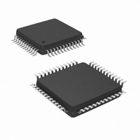
IC AC '97 AUDIO CODEC 48-LQFP
Manufacturer
National Semiconductor
Type
Audio Codec '97r
Specifications of LM4550BVH/NOPB
Data Interface
Serial
Resolution (bits)
18 b
Number Of Adcs / Dacs
2 / 2
Sigma Delta
Yes
Dynamic Range, Adcs / Dacs (db) Typ
90 / 89
Voltage - Supply, Analog
4.2 V ~ 5.5 V
Voltage - Supply, Digital
3 V ~ 5.5 V
Operating Temperature
-40°C ~ 85°C
Mounting Type
Surface Mount
Package / Case
48-LQFP
Audio Codec Type
Stereo
No. Of Adcs
2
No. Of Dacs
2
No. Of Input Channels
8
No. Of Output Channels
3
Adc / Dac Resolution
18bit
Sampling Rate
48kSPS
Interface Type
Serial
Supply Voltage Range
3V To 5.5V, 4.2V
Rohs Compliant
Yes
Lead Free Status / RoHS Status
Lead free / RoHS Compliant
Other names
*LM4550BVH
*LM4550BVH/NOPB
LM4550BVH
*LM4550BVH/NOPB
LM4550BVH
Available stocks
Company
Part Number
Manufacturer
Quantity
Price
Company:

Part Number:
LM4550BVH/NOPB
Manufacturer:
STM
Quantity:
1 872
Company:
Part Number:
LM4550BVH/NOPB
Manufacturer:
Texas Instruments
Quantity:
10 000


Register Descriptions
EXTENDED AUDIO STATUS/CONTROL REGISTER
(2Ah)
This read/write register provides status and control of the
variable sample rate capabilities in the LM4550. Setting the
LSB of this register to "1" enables Variable Rate Audio (VRA)
mode and allows DAC and ADC sample rates to be pro-
grammed via registers 2Ch and 32h respectively.
SAMPLE RATE CONTROL REGISTERS (2Ch, 32h)
These read/write registers are used to set the sample rate
for the left and right channels of the DAC (PCM DAC Rate,
2Ch) and the ADC (PCM ADC Rate, 32h). When Variable
Rate Audio is enabled via bit 0 of the Extended Audio
Control/Status register (2Ah), the sample rates can be pro-
grammed, in 1 Hz increments, to be any value from 4 kHz to
48 kHz. The value required is the hexadecimal representa-
tion of the desired sample rate, e.g. 8000
is a list of the most common sample rates and the corre-
sponding register (hex) values.
CHAIN-IN CONTROL REGISTER (74h)
This read/write register is only needed when using the Chain
In feature. This feature goes beyond the AC ’97 specification
and is not required for standard AC Link operation. The two
LSBs of this register default to the Codec Identity (ID1, ID0)
after reset. This default state corresponds to standard AC
Link operation where the output of codec pin 8 (SDATA_IN)
carries the AC Link Input Frames back to the controller from
the codec.
If the two LSBs differ from the Codec Identity (register 28h
describes the Codec Identity), then the signal present at CIN
(pin 48) is switched through to the SDATA_IN (pin 8) output.
In this fashion, Secondary codecs can be chained together
by connecting one codec’s SDATA_IN pin to the next co-
dec’s CIN pin. This has the end result of only requiring a
single SDATA_IN pin at the controller rather than the stan-
dard one SDATA_IN pin per codec. Note, however, that the
NC/DV
NC/DV
Default: 0000h
Pin 46
(ID1#)
GND
GND
VRA
BIT
DD
DD
SR15:SR0
*BB80h
NC/DV
NC/DV
AC44h
1F40h
3E80h
2B11h
5622h
Pin 45
*0 = VRA off (Frame-rate sampling)
(ID0#)
GND
GND
1 = VRA on
Common Sample Rates
DD
DD
D15,28h
(ID1)
0
0
1
1
Function
D14,28h
(ID0)
Sample Rate (Hz)
0
1
0
1
(Continued)
*48000
16000
22050
44100
10
11025
8000
Codec Identity
Primary
Secondary 1
Secondary 2
Secondary 3
= 1F40h. Below
Mode
25
chained codecs time-share the bandwidth of the SDATA_IN
signal under allocation from the controller.
The first codec in the chain (nearest the controller) will have
access to the full bandwith of SDATA_IN following a system
reset (Cold Reset for each codec). To access any other
codec in the chain, the controller must write a suitable value
(i.e. the Identity of the target codec) to the Chain-In Control
register (74h) of each intervening codec in the chain.
The last codec in the serial chain (furthest from the control-
ler) should have its CIN pin connected to digital ground.
When writing software drivers, care should be taken to avoid
any problems that could occur when this last codec in the
chain is set to pass a CIN signal when there is none to pass.
Different controllers may handle an input of all 0s differently
and leaving the CIN pin floating should definitely be avoided.
VENDOR ID REGISTERS (7Ch, 7Eh)
These two read-only (4E53h, 4350h) registers contain Na-
tional’s Vendor ID and National’s LM45xx codec version
designation. The first 24 bits (4Eh, 53h, 43h) represent the
three ASCII characters “NSC” which is National’s Vendor ID
for Microsoft’s Plug and Play. The last 8 bits are the two
binary coded decimal characters, 5, 0 and identify the codec
to be an LM4550.
RESERVED REGISTERS
Do not write to reserved registers. In particular, do not write
to registers 24h, 5Ah and 7Ah. All registers not listed in the
LM4550 Register Map are reserved. Reserved registers will
return 0000h if read.
Low Power Modes
The LM4550 provides 7 bits to control the powerdown state
of internal analog and digital subsections and clocks. It also
provides one bit intended to control an external analog
power amplifier. These 8 bits (PR0 – PR6, EAPD) are the 8
MSBs of the Powerdown Control/Status register, 26h. The
status of the four main analog subsections is given by the 4
LSBs in the same register, 26h.
The powerdown bits are implemented in compliance with AC
’97 Rev 2.1 to support the standard device power manage-
ment states D0 – D3 as defined in the ACPI and PCI Bus
Power Management specification.
PR0 controls the powerdown state of the ADC and associ-
ated sampling rate conversion circuitry. PR1 controls power-
down for the DAC and the DAC sampling rate conversion
circuitry. PR2 powers down the mixer circuits (MIX1, MIX2,
National 3D Sound, Mono Out, Line Out). PR3 powers down
V
powers down the AC Link Digital Interface – see Figure 8 for
signal powerdown timing. PR5 disables internal clocks but
leaves the crystal oscillator and BIT_CLK running (needed
for minimum Primary mode powerdown dissipation in multi-
codec systems). PR6 powers down the Headphone ampli-
fier. EAPD controls the External Amplifier PowerDown pin
(pin 47).
After a subsection has undergone a powerdown cycle, the
appropriate status bit(s) in the Powerdown Control/Status
register (26h) must be polled to confirm readiness. In par-
REF
BIT#
1,0
in addition to all the same mixer circuits as PR2. PR4
*(bit1,bit0) = (ID1,ID0): Chain-In off
(bit1,bit0) ≠ (ID1,ID0): Chain-In on
Function
www.national.com
Related parts for LM4550BVH/NOPB
Image
Part Number
Description
Manufacturer
Datasheet
Request
R

Part Number:
Description:
IC,Soundcard Circuits,QFP,48PIN,PLASTIC
Manufacturer:
National Semiconductor

Part Number:
Description:
Ac ?97 Rev 2.1 Multi-channel Audio Codec With Stereo Headphone Amplifier, Sample Rate Conversion And National 3d Sound
Manufacturer:
National Semiconductor Corporation
Datasheet:
Part Number:
Description:
National Semiconductor [8-Bit D/A Converter]
Manufacturer:
National Semiconductor
Datasheet:
Part Number:
Description:
National Semiconductor [Media Coprocessor]
Manufacturer:
National Semiconductor
Datasheet:
Part Number:
Description:
Digitally Controlled Tone and Volume Circuit with Stereo Audio Power Amplifier, Microphone Preamp Stage and National 3D Sound
Manufacturer:
National Semiconductor
Datasheet:
Part Number:
Description:
Digitally Controlled Tone and Volume Circuit with Stereo Audio Power Amplifier, Microphone Preamp Stage and National 3D Sound
Manufacturer:
National Semiconductor
Datasheet:
Part Number:
Description:
AC97 Rev 2 Codec with Sample Rate Conversion and National 3D Sound
Manufacturer:
National Semiconductor
Part Number:
Description:
Manufacturer:
National Semiconductor
Datasheet:
Part Number:
Description:
Manufacturer:
National Semiconductor
Datasheet:
Part Number:
Description:
General Purpose, Low Voltage, Low Power, Rail-to-Rail Output Operational Amplifiers
Manufacturer:
National Semiconductor
Datasheet:
Part Number:
Description:
8-bit 20 MSPS flash A/D converter.
Manufacturer:
National Semiconductor
Datasheet:
Part Number:
Description:
Low Noise Quad Operational Amplifier
Manufacturer:
National Semiconductor
Datasheet:
Part Number:
Description:
Quad Differential Line Receivers
Manufacturer:
National Semiconductor
Datasheet:
Part Number:
Description:
Quad High Speed Trapezoidal? Bus Transceiver
Manufacturer:
National Semiconductor
Datasheet: