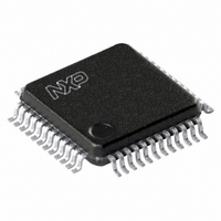
UCB1400BE,151 NXP Semiconductors, UCB1400BE,151 Datasheet - Page 13

UCB1400BE,151
Manufacturer Part Number
UCB1400BE,151
Description
IC AUDIO CODEC 3.3V 48-LQFP
Manufacturer
NXP Semiconductors
Type
Audio Codec '97r
Datasheet
1.UCB1400BEFE.pdf
(63 pages)
Specifications of UCB1400BE,151
Package / Case
48-LQFP
Data Interface
Serial
Resolution (bits)
20 b
Number Of Adcs / Dacs
2 / 2
Sigma Delta
No
S/n Ratio, Adcs / Dacs (db) Typ
97 / 91
Voltage - Supply, Analog
3 V ~ 3.6 V
Voltage - Supply, Digital
3 V ~ 3.6 V
Operating Temperature
-40°C ~ 85°C
Mounting Type
Surface Mount
Mounting Style
SMD/SMT
Lead Free Status / RoHS Status
Lead free / RoHS Compliant
Other names
935269304151
UCB1400BE-SNXP
UCB1400BE-SNXP
UCB1400BE-SNXP
UCB1400BE-SNXP
Available stocks
Company
Part Number
Manufacturer
Quantity
Price
Company:
Part Number:
UCB1400BE,151
Manufacturer:
NXP Semiconductors
Quantity:
10 000
Philips Semiconductors
9397 750 09611
Product data
8.3.4 AC-link low power mode
Table 3:
Slots 5 through 11:
UCB1400.
The AC-link signals can be placed in a low power mode. When the UCB1400’s PR4
bit is set to ‘1’ in the Power-down status and control register (0x26), both BIT_CLK
and SDATA_IN will be brought to, and held at, a logic LOW voltage level.
BIT_CLK and SDATA_IN are transitioned low immediately following the decode of the
write to Register 0x26 with PR4. When the AC ’97 Controller driver is at the point
where it is ready to program the AC-link into its low power mode, slots (1 and 2) are
assumed to be the only valid stream in the audio output frame.
The AC ’97 Controller should also drive SYNC and SDATA_OUT LOW after
programming UCB1400 AC ’97 to this low power, halted mode. The AC ’97 Controller
is required to drive and keep SYNC and SDATA_OUT LOW in this low power, halted
mode.
Once the UCB1400 has been instructed to halt BIT_CLK, a special ‘wake-up’ protocol
must be used to bring the AC-link to the active mode since normal audio output and
input frames cannot be communicated in the absence of BIT_CLK.
Bit
19-4
3-1
0
Fig 10. AC-link power-down timing.
GPIO
GPIO[15:0]
SDATA_OUT
Slot 12 definition
SDATA_IN
BIT_CLK
SYNC
Rev. 02 — 21 June 2002
All other audio input frame slots shall be stuffed with 0s by the
Name
Vendor rsrvd
GPIO_INT
prev. frame
prev. frame
slot 12
slot 12
TAG
TAG
Sense
in/out
in
Audio codec with touch screen controller
Write to
0x26
and power management monitor
Description
Modem GPIO as defined by the Intel
AC ’97 Component Specification .
Vendor optional.
GPIO_INT (uses same logic as
wake-up event)
Data
PR4
© Koninklijke Philips Electronics N.V. 2002. All rights reserved.
UCB1400
SN00244
13 of 63


