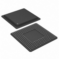
DS21FT42 Maxim Integrated Products, DS21FT42 Datasheet - Page 24

DS21FT42
Manufacturer Part Number
DS21FT42
Description
IC FRAMER T1 4X3 12CH 300-BGA
Manufacturer
Maxim Integrated Products
Datasheet
1.DS21FT42.pdf
(114 pages)
Specifications of DS21FT42
Controller Type
T1 Framer
Interface
Parallel/Serial
Voltage - Supply
2.97 V ~ 3.63 V
Current - Supply
225mA
Operating Temperature
0°C ~ 70°C
Mounting Type
Surface Mount
Package / Case
300-BGA
Lead Free Status / RoHS Status
Contains lead / RoHS non-compliant
Available stocks
Company
Part Number
Manufacturer
Quantity
Price
In non–multiplexed bus operation (MUX = 0), serves as the address bus. In multiplexed bus operation
(MUX = 1), these pins are not used and should be tied low.
In non–multiplexed bus operation (MUX = 0), serves as address Bit 6. In multiplexed bus operation
(MUX = 1), serves to demultiplex the bus on a positive–going edge.
Strap high to select Motorola bus timing; strap low to select Intel bus timing. This pin controls the
function of the RD*(DS*), ALE(AS), and WR*(R/W*) pins. If BTS = 1, then these pins assume the
function listed in parenthesis ().
RD* and DS* are active low signals. Note: DS is active high when MUX=1. Refer to bus timing
diagrams in section 25.
Selects which of the four framers to be accessed.
Must be low to read or write to the device. CS* is an active low signal.
WR* is an active low signal.
TEST ACCESS PORT PINS
Set high to 3–state all output and I/O pins (including the parallel control port) when FMS = 1 or when
FMS = 0 and JTRST* is tied low. Set low for normal operation. Ignored when FMS = 0 and JTRST* =
1. Useful in board level testing. FMS is tied to ground for the DS21FF42/DS21FT42.
Signal Name:
Signal Description:
Signal Type:
Signal Name:
Signal Description:
Signal Type:
Signal Name:
Signal Description:
Signal Type:
Signal Name:
Signal Description:
Signal Type:
Signal Name:
Signal Description:
Signal Type:
Signal Name:
Signal Description:
Signal Type:
Signal Name:
Signal Description:
Signal Type:
Signal Name:
Signal Description:
Signal Type:
A0 to A5, A7
Address Bus
Input
ALE(AS)/A6
A6 or Address Latch Enable (Address Strobe)
Input
BTS
Bus Type Select
Input
RD*(DS*)
Read Input (Data Strobe)
Input
FS0 AND FS1
Framer Selects
Input
CS*
Chip Select
Input
WR*( R/W*)
Write Input(Read/Write)
Input
TEST
3–State Control
Input
24 of 114


