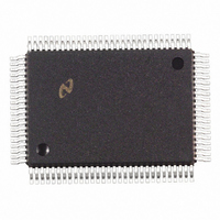
DP83902AVLJ National Semiconductor, DP83902AVLJ Datasheet - Page 37

DP83902AVLJ
Manufacturer Part Number
DP83902AVLJ
Description
IC CTRLR SER NETWORK IN 100PQFP
Manufacturer
National Semiconductor
Datasheet
1.DP83902AVJGNOPB.pdf
(70 pages)
Specifications of DP83902AVLJ
Controller Type
Serial Network Interface Controller
Interface
Serial
Voltage - Supply
4.75 V ~ 5.25 V
Current - Supply
140mA
Operating Temperature
0°C ~ 70°C
Mounting Type
Surface Mount
Package / Case
100-MQFP, 100-PQFP
Lead Free Status / RoHS Status
Contains lead / RoHS non-compliant
Other names
*DP83902AVLJ
Available stocks
Company
Part Number
Manufacturer
Quantity
Price
Company:
Part Number:
DP83902AVLJ
Manufacturer:
NS
Quantity:
2 500
Company:
Part Number:
DP83902AVLJ
Manufacturer:
RAYCHEM
Quantity:
2 500
Company:
Part Number:
DP83902AVLJ
Manufacturer:
Texas Instruments
Quantity:
10 000
Part Number:
DP83902AVLJ
Manufacturer:
NS/国半
Quantity:
20 000
11 0 Initialization Procedures
The ST-NIC must be initialized prior to transmission or re-
ception of packets from the network Power on reset is ap-
plied to the ST-NIC’s reset pin This clears sets the follow-
ing bits
The ST-NIC remains in its reset state until a Start Command
is issued This guarantees that no packets are transmitted
or received and that the ST-NIC remains a bus slave until all
appropriate internal registers have been programmed After
initialization the STP bit of the command register is reset
and packets may be received and transmitted
Initialization Sequence
The following initialization procedure is mandatory
10 Put ST-NIC in START mode (Command Register
11 Initialize the Transmit Configuration Register for the in-
Before receiving packets the user must specify the location
of the Receive Buffer Ring This is programmed in the Page
Start and Page Stop Registers In addition the Boundary
and Current Page Register must be initialized to the value of
the Page Start Register These registers will be modified
during reception of packets
1 Program Command Register for Page 0 (Command
2 Initialize Data Configuration Register (DCR)
3 Clear Remote Byte Count Registers (RBCR0 RBCR1)
4 Initialize Receive Configuration Register (RCR)
5 Place the ST-NIC in LOOPBACK mode 1 or 2 (Transmit
6 Initialize Receive Buffer Ring
7 Clear Interrupt Status Register (ISR) by writing 0FFH to
8 Initialize Interrupt Mask Register (IMR)
9 Program Command Register for page 1 (Command
Command Register (CR)
Interrupt Status (ISR)
Interrupt Mask (IMR)
Data Control (DCR)
Transmit Config (TCR)
22H)
tended value The ST-NIC is now ready for transmission
and reception
Register
Configuration Register
(BNDRY)
(PSTOP)
it
Register
III) Initialize CURRent pointer
II) Initialize Multicast Address Registers (MAR0– MAR5)
I) Initialize Physical Address Registers (PAR0 – PAR5)
Register
e
e
Page Start (PSTART)
21H)
61H)
e
02H or 04H)
Reset Bits
TXP STA
All Bits
LB1 LB0
Boundary Pointer
and Page Stop
RD2 STP
RST
LAS
Set Bits
e
37
12 0 Loopback Diagnostics
Three forms of local loopback are provided on the ST-NIC
The user has the ability to loopback through the deserializer
on the controller through the ENDEC module or the Trans-
ceiver Because of the half duplex architecture of the
ST-NIC loopback testing is a special mode of operation
with the following restrictions
Restrictions During Loopback
The FIFO is split into two halves one half is used for trans-
mission and the other for reception Only 8-bit fields can be
fetched from memory so two tests are required for 16-bit
systems to verify integrity of the entire data path During
loopback the maximum latency from the assertion of BREQ
to BACK is 2 0 s Systems that wish to use the loopback
test but do not meet this latency can limit the loopback to
7 bytes without experiencing underflow Only the last
8 bytes of the loopback packet are retained in the FIFO
The last 8 bytes can be read through the FIFO register
which will advance through the FIFO to allow reading the
receive packet sequentially
When in word-wide mode with Byte Order Select set the
loopback packet must be assembled in the even byte loca-
tion as shown below (Loopback only operates with byte
wide transfers )
When in word-wide mode with Byte Order Select low the
following format must be used for the loopback packet
Note When using loopback in word mode 2n bytes must be programmed in
Destination Address
Source Address
TBCR0 1 Where n
odd location
Length
Data
CRC
e
e
actual number of bytes assembled in even or
(6 Bytes) Station Physical Address
Appended by ST-NIC
if CRC
e
46 to 1500 Bytes
2 Bytes
e
‘‘0’’ in TCR
l
TL F 11157 – 54
TL F 11157 – 55


