AD9958BCPZ Analog Devices Inc, AD9958BCPZ Datasheet - Page 10
AD9958BCPZ
Manufacturer Part Number
AD9958BCPZ
Description
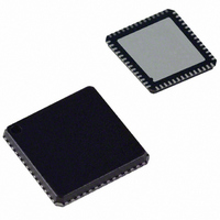
IC DDS DUAL 500MSPS DAC 56LFCSP
Manufacturer
Analog Devices Inc
Datasheet
1.AD9958BCPZ.pdf
(44 pages)
Specifications of AD9958BCPZ
Design Resources
Low Jitter Sampling Clock Generator for High Performance ADCs Using AD9958/9858 and AD9515 (CN0109) Phase Coherent FSK Modulator (CN0186)
Resolution (bits)
10 b
Master Fclk
500MHz
Tuning Word Width (bits)
32 b
Voltage - Supply
1.71 V ~ 1.96 V
Operating Temperature
-40°C ~ 85°C
Mounting Type
Surface Mount
Package / Case
56-LFCSP
Pll Type
Frequency Synthesis
Frequency
500MHz
Supply Current
105mA
Supply Voltage Range
1.71V To 1.89V
Digital Ic Case Style
LFCSP
No. Of Pins
56
Operating Temperature Range
-40°C To +85°C
Lead Free Status / RoHS Status
Lead free / RoHS Compliant
For Use With
AD9958/PCBZ - BOARD EVALUATION FOR AD9958
Lead Free Status / Rohs Status
Compliant
Available stocks
Company
Part Number
Manufacturer
Quantity
Price
Company:

Part Number:
AD9958BCPZ
Manufacturer:
ADI
Quantity:
636
Part Number:
AD9958BCPZ
Manufacturer:
ADI/亚德诺
Quantity:
20 000


AD9958
Pin No.
24
27
28, 32, 34, 38
40, 41, 42, 43
46
47
48
49
50
51, 52, 53
54
1
I = input, O = output.
Mnemonic
CLK_MODE_SEL
LOOP_FILTER
NC
P0, P1, P2, P3
I/O_UPDATE
CS
SCLK
DVDD_I/O
SDIO_0
SDIO_1, SDIO_2,
SDIO_3
SYNC_CLK
I/O
I
I
N/A
I
I
I
I
I
I/O
I/O
O
1
Active Low Chip Select. Allows multiple devices to share a common I/O bus (SPI).
3.3 V Digital Power Supply for SPI Port and Digital I/O.
Data Pin SDIO_0 is dedicated to the serial port I/O only.
Description
Control Pin for the Oscillator Section. Caution: Do not drive this pin beyond 1.8 V.
When high (1.8 V), the oscillator section is enabled to accept a crystal as the
REF_CLK source. When low, the oscillator section is bypassed.
Connects to the external zero compensation network of the PLL loop filter.
Typically, the network consists of a 0 Ω resistor in series with a 680 pF capacitor
tied to AVDD.
No Connection.
Data pins used for modulation (FSK, PSK, ASK), to start/stop for the sweep
accumulators, or used to ramp up/ramp down the output amplitude. The data is
synchronous to the SYNC_CLK (Pin 54). The data inputs must meet the setup and
hold time requirements to the SYNC_CLK. The functionality of these pins is
controlled by profile pin configuration (PPC) bits (FR1[14:12]).
A rising edge transfers data from the serial I/O port buffer to active registers.
I/O_UPDATE is synchronous to the SYNC_CLK (Pin 54). I/O_UPDATE must meet the
setup and hold time requirements to the SYNC_CLK to guarantee a fixed pipeline
delay of data to the DAC output; otherwise, a ±1 SYNC_CLK period of pipeline
uncertainty exists. The minimum pulse width is one SYNC_CLK period.
Serial Data Clock for I/O Operations. Data bits are written on the rising edge of
SCLK and read on the falling edge of SCLK.
Data Pin SDIO_1, Data Pin SDIO_2, and Data Pin SDIO_3 can be used for the serial
I/O port or used to initiate a ramp-up/ramp-down (RU/RD) of the DAC output
amplitude.
The SYNC_CLK runs at one fourth the system clock rate. It can be disabled. I/O_UPDATE
or data (Pin 40 to Pin 43) is synchronous to the SYNC_CLK. To guarantee a fixed
pipeline delay of data to DAC output, I/O_UPDATE or data (Pin 40 to Pin 43) must
meet the setup and hold time requirements to the rising edge of SYNC_CLK;
otherwise, a ±1 SYNC_CLK period of uncertainty exists.
Rev. A | Page 10 of 44
Related parts for AD9958BCPZ
Image
Part Number
Description
Manufacturer
Datasheet
Request
R

Part Number:
Description:
BOARD EVALUATION FOR AD9958
Manufacturer:
Analog Devices Inc
Datasheet:
Part Number:
Description:
BOARD EVALUATION FOR AD9958
Manufacturer:
Analog Devices Inc
Datasheet:


Part Number:
Description:
±1.7g Dual-Axis IMEMS Accelerometer Evaluation Board
Manufacturer:
Analog Devices Inc
Datasheet:

Part Number:
Description:
Inertial Sensor Evaluation System
Manufacturer:
Analog Devices Inc
Datasheet:
Part Number:
Description:
Manufacturer:
Analog Devices Inc
Datasheet:
Part Number:
Description:
Manufacturer:
Analog Devices Inc
Datasheet:
Part Number:
Description:
Manufacturer:
Analog Devices Inc
Datasheet:
Part Number:
Description:
Manufacturer:
Analog Devices Inc
Datasheet:
Part Number:
Description:
Manufacturer:
Analog Devices Inc
Datasheet:
Part Number:
Description:
Manufacturer:
Analog Devices Inc
Datasheet:
Part Number:
Description:
Manufacturer:
Analog Devices Inc
Datasheet:
Part Number:
Description:
Manufacturer:
Analog Devices Inc
Datasheet: