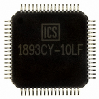
ICS1893Y-10LF IDT, Integrated Device Technology Inc, ICS1893Y-10LF Datasheet - Page 106

ICS1893Y-10LF
Manufacturer Part Number
ICS1893Y-10LF
Description
PHYCEIVER LOW PWR 3.3V 64-TQFP
Manufacturer
IDT, Integrated Device Technology Inc
Series
PHYceiver™r
Type
PHY Transceiverr
Specifications of ICS1893Y-10LF
Protocol
MII
Voltage - Supply
3.14 V ~ 3.47 V
Mounting Type
Surface Mount
Package / Case
64-TQFP, 64-VQFP
Lead Free Status / RoHS Status
Lead free / RoHS Compliant
Number Of Drivers/receivers
-
Other names
1893Y-10LF
800-1935-5
ICS1893Y-10LF
800-1935-5
ICS1893Y-10LF
Available stocks
Company
Part Number
Manufacturer
Quantity
Price
Company:
Part Number:
ICS1893Y-10LF
Manufacturer:
ICS
Quantity:
5 978
Company:
Part Number:
ICS1893Y-10LF
Manufacturer:
IDT, Integrated Device Technology Inc
Quantity:
10 000
Company:
Part Number:
ICS1893Y-10LFT
Manufacturer:
IDT, Integrated Device Technology Inc
Quantity:
10 000
9.3.2 Multi-Function (Multiplexed) Pins: PHY Address and LED Pins
ICS1893 Rev C 6/6/00
Table 9-3
pins).
Note:
1. During either a power-on reset or a hardware reset, each multi-function configuration pin is an input
2. A software reset does not affect the state of a multi-function configuration pin. During a software reset,
3. Each multi-function configuration pin must be pulled either up or down with a resistor to establish the
4. As outputs, the asserted state of a multi-function configuration pin is the inverse of the sense sampled
Note:
Table 9-3.
P0AC
Name
Pin
that is sampled when the ICS1893 exits the reset state. After sampling is complete, these pins are
output pins that can drive status LEDs.
all multi-function configuration pins are outputs.
address of the ICS1893. LEDs placed in series with these resistors provide a designated status
indicator.
Caution:
during reset. This inversion provides a signal that can illuminate an LED during an asserted state. For
example, if a multi-function configuration pin is pulled down to ground through an LED and a
current-limiting resistor, then the sampled sense of the input is low. To illuminate an LED for the
asserted state requires the output to be high.
ICS1893 Data Sheet - Release
Each of these pins monitor the data link by providing signals that directly drive LEDs.
lists the pins for the multi-function group of pins (that is, the multiplexed PHY Address / LED
Number
PHY Address and LED Pins
Pin
55
All pins listed in
Input or
Output
Type
Pin
Copyright © 2000, Integrated Circuit Systems, Inc.
All rights reserved.
PHY (Address Bit) 0 / Activity LED.
For more information on this pin, see
As an input pin:
As an output pin:
Caution:
•
•
•
Table 9-3
This multi-function configuration pin is:
– An input pin during either a power-on reset or a hardware reset. In
– An output pin following reset. In this case, this pin provides link status
This pin establishes the address for the ICS1893. When the signal on
this pin is logic:
– Low, that address bit is set to logic zero.
– High, that address bit is set to logic one.
When the signal on this pin is:
– De-asserted, this state indicates the ICS1893 does not have a link.
– Asserted, this state indicates the ICS1893 has a valid link.
this case, this pin configures the ICS1893 when it is in either
hardware mode or software mode.
of the ICS1893.
must not float.
This pin must not float. (See the notes at
“ Multi-Function (Multiplexed) Pins: PHY Address and LED
Pins”
106
.)
Chapter 9 Pin Diagram, Listings, and Descriptions
Pin Description
Section 6.8, “ Status Interface”
Section 9.3.2,
June, 2000
.


